


")

Designed my machine is addressed to farmers and owners of summer cottages with self-contained water system, major components of which are water source (river, lake, well or borehole), electric Yes water tank. From analogues of this development is characterized in that in addition to performing basic functions - manage the pump - makes it quite successfully solve even objectives for the protection of objects. This unusual flexibility is achieved not complication of a circuit diagram of the device, and due to the quick change sensors, which serve not only multilevel submersible electrodes, and a photoconductive or thin working tensile wire.
Operation of machine in the system of local water supply can be reduced to the actuation electromagnetic relay K1. It's getting power from the transformer T1 (via diode bridge VD1 - VD4 and VS1 thyristor, which is controlled by the sensor SL1 water level) enables or disables the pump.
For example, water in the tank is so small that when you switch the toggle switch SA2 in the position of "Pump" all the electrodes SL1 to be open. Chain control thyristor, in fact, idle. Hence, the VS1 and current through the winding relay K1 does not flow, and the outlet ХS1 through the normally closed contacts of K1.1 serves network 220 In, causing the system to replenish the water tank. Continues this is as long as the latter does not reach the electrode In the sensor SL1. It high, the achievement of which the thyristor is opened and the current flowing through VS1 and the coil K1, triggers the relay. Rasikas, the contacts K1.1 switch off the electric pump. Simultaneously, K1 are closed.2, by introducing into the circuit control thyristor electrode pair A-C sensor SL1 and providing automatic maintenance of the desired water level in the tank.
Indeed, with the fall of the water level below the minimum allowable open electrode pair A-C. This will cause a momentary closing of the thyristor and the de-energization of the relay, its normally closed contacts will be served the voltage supply to the pump. Engaged in work that will fill up the tank. And again the system will go into standby mode once the water level to drop. The water level sensor in the tank are three l-shaped metal plate, mounted on the float - a stand-alone basis.
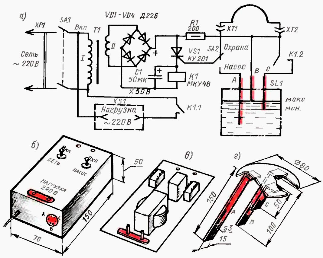
Schematic (a) a self-made machine, which is water day shakes, and at night serves as a security device, the placement of its main parts in case (b), on the circuit Board(b), and an embodiment of a submersible sensor (g) water level (click to enlarge)
When a switch SА2 to "Guard" the sensor is stretched subtle, hidden from the uninitiated wire (loop) between terminals 1 and HT. Undamaged wire supplies a control voltage for opening thyristor VS1 and the relay, which holds the normally open contacts K1.1 in the power circuit of the load. As the last appears not pump, and a light or audible signal (e.g., light, siren or bell). Then to eat when on protected sites is all right, the voltage-XS1 missing and the alarm signal is not received. With the fringe of the plume passage the current through the thyristor and the relay coil is stopped, and through the normally closed the contacts K1.1 turn on the detector.
It should be noted that for the Assembly of such a device would not require expensive and scarce radio components. The switches SA1, SA2 type TB2-1 or TP1-2; rectifier diodes - D226 or similar (can be limited to a finished bridge CC…KTS405). As capacitor C1 is suitable electrolytic capacitance of about 50 microfarads working on a voltage less than 50 V. the Resistor R1 is the most common poluvattny (e.g., MLT-0,5); and the thyristor VS1 - KU (KU).
With the relay and the selection of the corresponding transformer is more difficult. If not will be under the hands mentioned in the scheme MCU for 12, 24 or 36 V, with success suitable TCE (TCE). Measure the voltage, should be selected for relay available step-down transformer, for Example, TN or even "vychodni" the old tube receiver.
If not ready a suitable transformer, you can use any designed to work on 220 V. by Measuring the voltage on the secondary winding, its wound, considering all the removed coils. Then, having determined the conversion factor (the number of turns per 1 In), wind a new coil II, match the voltage of the relay. Connecting to a modified the transformer relay via a rectifier bridge and plugging into the network, is satisfied definition of actuation of contacts K1.1 and the absence of overheating of the windings.
The Assembly of the electronic parts of the instrument carry out on a sheet of Micarta or fiberglass. Mounting - hinged, with subsequent placement of the finished product in a plastic box of suitable size.
Plume, as mentioned, is thin insulated or bare wire appropriate length, have secretly so that attackers, nothing not the Veda that are contributing to the surveillance system, hooked and tore it.
Author: Kochkin Yu.