


")

This detector is simple to manufacture and operate. To make it even inexperienced Amateurs.
Diagram of the transmitter
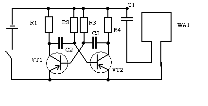
Details:
VT1, VT2 - MP39 - MP42 (with any letter index)
R2, R3 - 100 Ohm
R1, R4 - 4, 7 ohms
C1 - 0, 01 pF
C2 - 0, 02 pF
C 3 - 0, 05 pF
Power - the element type C (slightly more than AA)
WA1 - 50 turns of PEV - 2 0, 12 on the frame 10*10*10*10 cm (square)
Switch - any.
Frequency - 1 kHz
The signal amplitude is 0, 5 In
The receiver circuit
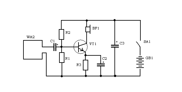
Details:
WA2 is the same, WA1
C1, C2, C3 47 UF 16 V
R1 - 3 K
R2 10 kω
R3 - 300 Ohm
BF1 - headphones-60 - 100 Ohm
VT1 - KT315B
GB1 - three AA-size batteries connected in series
SA1 - any
Coils can be placed like so:
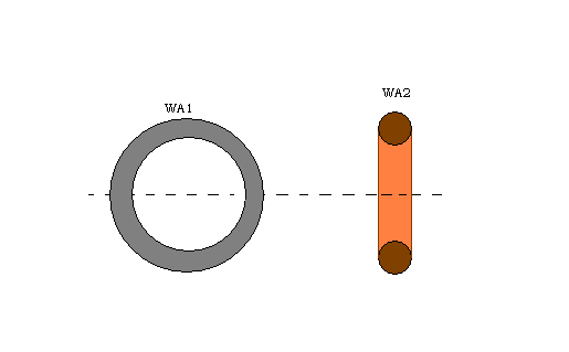
In this embodiment, the detector can be used as a detector. If you need to trace the wiring in the wall, should the transmitter antenna is placed next you have found the end of the wire, and the receiving antenna led on the wall. In General, the number of applications of this device are limited only by your imagination.
Author: P. Petrukhin, Petrukhin.Pavel [dog] mail.ru; Publication: www.cxem.net