When construction work is often required to accurately determine parallelism the horizontal surface relative to the earth. In some power tools (electric drills, rotary hammers, etc.) there is a small "level", a built-in shell (liquid filled glass cone with bubble inside). The position of the bubble determines the tilt of the device relatively horizontal surface. Such devices have been called "gyroscopes". They are quite common in many areas of production, construction etc and electronic gyroscopes - converters tilt and angular velocity into an electrical signal.
Electronic gyroscopes brand "ENC-03J" and "ENC-03M" appeared in the market recently. They serve as sensors state changes in the cameras and "tough" cameras to compensate hand-shake when shooting, and to determine their own movement. Electronic gyroscope has a high response speed (minimum inertia), low voltage (2.7..5.5 V depending on the model) and low current consumption (typically 5.15 mA). The linearity - ±5%, in a range temperature-5...+75°C. unlike its mechanical counterpart, it is compact and lightweight (size - 15x8x4 mm), weight (depending on model) 1.. 20 G. not contains fragile materials that has shockproof and vibration-proof housing. Electronic gyroscopes are produced even in the CHIP design. allow the use of them in miniature devices. On the basis of such an electronic device-sensor you can create a simple device control "horizontally".
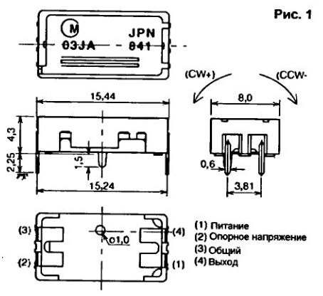
The sensor is piezoelectric gyroscope "ENC-03J (Fig.1) manufactured by "Murala".

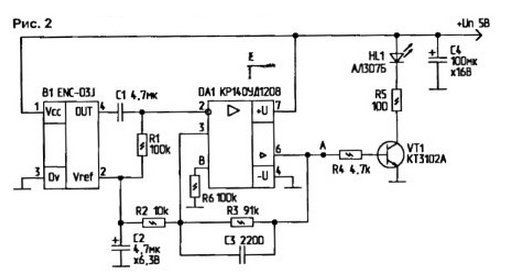
I bought it in shop of radio components "Micronica" in St. Petersburg. When the horizontal position of the device the DC voltage at pin 4 of the sensor 61 (Fig.2) is 1.3...1.4 V (At Un=5 V). Operational amplifier DA1 is enabled in the circuit with a unity gain. On pin 2 receives voltage V1 comparison low-pass filter R2-C2. which simultaneously performs the role of feedback operational amplifier.

When you change the horizontal position sensor output voltage (pin 4) B1 is changed in accordance with the conversion factor of 0.67 mV/° / sec. The frequency of polling the status of the sensor is about 50 Hz. The maximum angular velocity relatively horizontal position - ±300° / sec. Separation capacitor C1 forms together with the resistor R1 frequency filter with a bandwidth slice about 0.3 Hz, and does not pass the DC component of the voltage at the input of the operational amplifier DA1. When you change the horizontal position sensor output DA1 (output 6) you receive the high voltage level, which opens the switching transistor VT1. Consequently HL1 led is lit
Details. All fixed resistors - type MLT-0.25, MF-25. The Capacitor C1 Is nonpolar. K10-17, C2 - tantalum oxide. K52-K53-X. C3 - km-6B. C4 - K50-20. If you use a standalone power source (battery or battery), C4 from the circuit can be eliminated. Led - any (AL307 or similar) For best visual control, you can put a flashing led instead the operational amplifier CRUD you can apply COD Transistor VT1 - any silicon n-p-n with a gain of more than 40. A power source for the device is stable, with a constant voltage of 3.. 5 V Current consumption deliverer FNC-03J does not exceed 15 mA.
The device is in adjustment not needed In connection with high sensitivity piezoceramic sensor B1 it is necessary to firmly attach it to the body the device, which, in turn, should be as smooth horizontal surface When mounting the components do not overheat the conclusions of the sensor (the soldering time is not more than 1). To use the device easily. It just installed on a controlled surface, if it is assumed tilt control) or placed in a controlled environment (not liquid) to assess vibration.
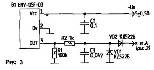
When used as a vibration sensor related device ENV-05F-03 the parameters of the device are improved (increased accuracy and sensitivity). Negative of the change may be the maximum angular velocity. This device it is smaller (±80°), but with this sensor does not need operational amplifier. The switching circuit ENV-05F-03 shown in Fig.3. The sensor has only three pins. Silicon diodes VD1, VD2 assembled a voltage Converter.

The output of the device can be connected to the control node, for example, to point a (Fig.2).
Author: A. Kashkarov, G. C Petersburg


