The indicator move air (IPV) is a device that can to perform different functions:
- of the indicator opening (collapse) vents, Windows or doors sudden impulse wind;
- signaling the availability of a draft;
- indicator exceeding a threshold speed of the air in enclosed spaces;
- signaling the presence of thrust in a vent.
Apply IPV suitable for remote control of movement of air, therefore, the sensor with the circuit Board and power source can be located in one the room and the led-indicator - somewhere else. For example, to to control the absence of a draft in the nursery, the led can be put in the parents ' bedroom or the kitchen. A loud cry or the cry of a child also includes led-indicator, warning of an "emergency" situation.
The device can be embedded in a badge to highlight depicted on character. At the disco or youth "the gathering" this icon will be effectively "wink" to the beat of music.
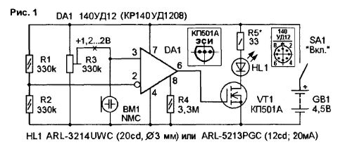
IPV (Fig.1) consists of a miniature microphone, of the comparator, the current key is a field effect transistor and the emitter led high brightness. The microphone WM operating mode specifies a trimming resistor R3. The comparator assembles the elements of R1...R3, DA1. Current key made on transistor VT1. In the circuit flow VT1 consistently with led HL1 included current limiting resistor R5. Resistor R4 sets the mode of the programmable the operational amplifier DA1.

On closure of switch SA1 battery voltage GB1 comes to IPV, and the device is in eco standby mode. The divider R1-R2 sets the reference voltage close to 0.5 u pit inverting input (pin 2) DA1. The resistor R3 and the microphone WM form a second voltage divider, the signal from mid-point which is fed to the non-inverting input (pin 3) DA1. When the advent of air flow, causing noise in the microphone, on upper circuit the output VM see a surge of positive polarity. And if the amplitude of these bursts exceeds the reference voltage level (0.5 u pit) the output (pin 6) DA1 there is a voltage close to the supply voltage. Oh without the feedback resistor, thereby maximizing the ratio gain, and the OS performs the function of the comparator, i.e., it compares the levels the voltage at the inputs and outputs the comparison result in the form of pulses or low a high level at the output.
If the voltage on the direct (noninverting) input more. than the inverting, the output voltage of the shelter tends to+u pit. But if the voltage on the direct input less than the inverting, the output of the OC - potential common wire (in the case a single supply). The maximum output voltage of approximately 1 DA1 In less than u pit VT1 Transistor switch allows Easy<20 and does not require cocoordinating resistor in the circuit of the shutter. During the positive pulses polarity transition opens the source-drain VT1, and HL1 led is brightly lit. Resistor R5 limits flowing in the load current to rated current LEDs HL1 (20 mA).
Configuring IPV consists of setting the bias voltage (+1,2...2) on the output 3 DA1. Lower voltage corresponds to lower sensitivity of IPV. When the voltage is less than +1.2 V sensitivity IPV drops sharply.
Assembled without errors from the healthy elements of the device begins to work immediately after configuring. To clarify the magnitude of the operating current through the led HL1 can the selection of R5. For this circuit flow is switched on the meter and the valve VT1 temporarily disconnected from the output DA1 and connected to-u pit the Resistance of R5 changes. to the current through HL1 does not exceed the maximum. When using unknown LEDs you can use the rule: current up to 10 mA is valid for almost all types of LEDs. Note that some super-vivid LEDs have a higher compared to "traditional* LEDs (AL307, etc.) operating voltage (3...4).
In IPV resistors are used OMLT, the trimmer R3 - SDR-38A. The SA1 toggle-switch - MTS-102, particularly miniature SMTS-102 or slide, for example, from an old calculator. Replacement DA1 (in battery operation) other OS, except COD, impractical. Transistor VT1 can be replaced by CP, CP with any alphabetic indices. HL1 led white ARL-3214UWC (20cd. diameter 3 mm) is replaced by, for example, super-vivid green 10G4DHCBB20 (4 chips in one the case, 3,8 V. 80 mA) or, in extreme cases, a low-power high-brightness luminescence, for example, emerald TTL 500G3VC-2 (3.5 V, 20 mA) with built-in lens. The microphone WM - electret may be replaced by similar, for example, particularly miniature XF-18D (d=6 MM. h=3.8 mm).
IPV is placed on the PCB of one-sided glass fiberglass dimensions 34x12x1,5 mm. the Drawing Board is shown in Fig.2, and the arrangement of elements in Fig.3.

The diameter of the holes on the circuit Board under the chip is 0.7...0.8 mm. under other parts - 0,8...1 mm, under connecting wires - 1...1.2 mm Board IPV to reduce the size not has mounting holes and is inserted into the body on friction. Figure printed conductors can be transferred onto the copper foil by thermal transfer method (1] or translate through carbon paper and circle acid-resistant permanent marker “Centropen 2846 SE PERMANENT", etc.). as well as a marker for signing computer CD-ROM drive,
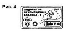
The IPV case may be improvised. Its dimensions are determined mainly sizes of used batteries or batteries. Author version posted IPV in a plastic soap dish in rectangular shape size 105x68x36 mm with glued it and secure with tape paper hapishanebig (Fig.4) printed on a color printer. Feeds on IPV from "flat" battery 3R12G or 3-4 batteries D-0.26 D (diameter 25 mm).

Depending on the appointment of IPV. the microphone VM is installed inside the case or out through the connector. Connection cables - unshielded. length 0.5 m.
Literature
Author: A. Oznobishin, Irkutsk


