


")

In the repair and wiring is often a need measure the voltage to determine the phase and neutral wires, "to ring" chain no breakages or short circuits. The indicator - pointer-phase will always be on hand, and the use of avometra uncomfortable for these purposes because of the need to switch modes.
The way out is to build the proposed device (see figure) consisting of led scale voltages, node control the conductivity of electric circuits ("continuity"), the AC voltage indicator and pointer phase wires.
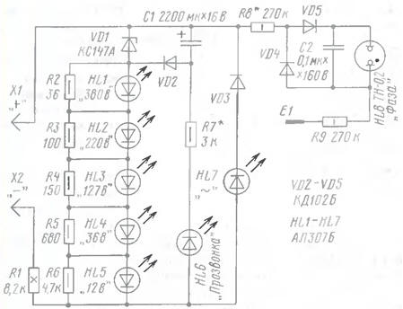
Led scale performed on the LEDs HL1-HL5 and the resistors R2 - R6, shunt LEDs, and has five grades standard voltages. Work scale is based on the ignition of a specific led when the voltage drops to shunt the resistor of about 1.7 V. the Circuit VD3HL7 serves to indicate AC voltage on the probes of the probe and return, compared to defined in the diagram, the polarity of the DC voltage on them.
The node control the conductivity consists of the storage capacitor C1 relatively large capacity, a chain VD1VD2 charging it and the readout circuit R7HL6. When connecting the test leads to the source of DC voltage for a few seconds the capacitor is charged through the diode VD2 voltage from falling on the Zener diode VD1. The probe is ready to "continuity test" circuits. If the probes touch a working circuit, the discharge current of the capacitor will flow through the resistor R1, the led and HL6 the resistor R7. The led will be lit. As the capacitor is discharged brightness LEDs will fall. On a single charge of the capacitor can be done 8-12 checks.
The pointer of the phase conductor is built on a relaxation oscillator Touching finger sensor E1, connect any leads to the phase conductors. Rectified diodes VD4, VD5 voltage charges the capacitor C2. When the voltage across it will reach a specific value will flash neon lamp HL8. Capacitor discharges through it, the process is repeated.
LEDs - shown on the diagram or their foreign counterparts, for example, L-63IT It is desirable that they were close on the parameters, a HL6 - with a maximum the luminous efficiency at low current. Together printed on the circuit a Zener diode can to be CSA or DB. Capacitor C1 - C50-35 or its foreign equivalent (for example, manufactured by Jamicon). Resistors R2-R9 - MLT appropriate power R1 - sew, C5-37 power not less than 8 W (in the extreme case can set of six series-connected resistors MLT-2 resistance of 1.3 kω).
The device is mounted in two housings of dielectric material in the form equal-sized probes. One probe is placed a resistor R1, in another the rest of the device. The probes have a pointed tip with a diameter of 3 and length 20 mm. the Probes are connected by a flexible wire in double insulation, designed for a voltage of not less than 380 V.
When establishing a tester and working with it should be taken precautions because details of the probe may be at high voltage!
If all parts are in good working order and installed correctly, the probe can be used immediately. However, you may have to pick up the resistor R7, to achieve a clear burning HL6 led (when connected between the probes of the resistor 300…400 Ohms). But it greatly reduce the resistance should not be, because this will cause a rapid discharge of the storage capacitor. And in order to achieve clearly distinguishable neon lamp flashes, enough to pick up a resistor R8.
Author: V. Sorokov, Sergiev Posad, Moscow region