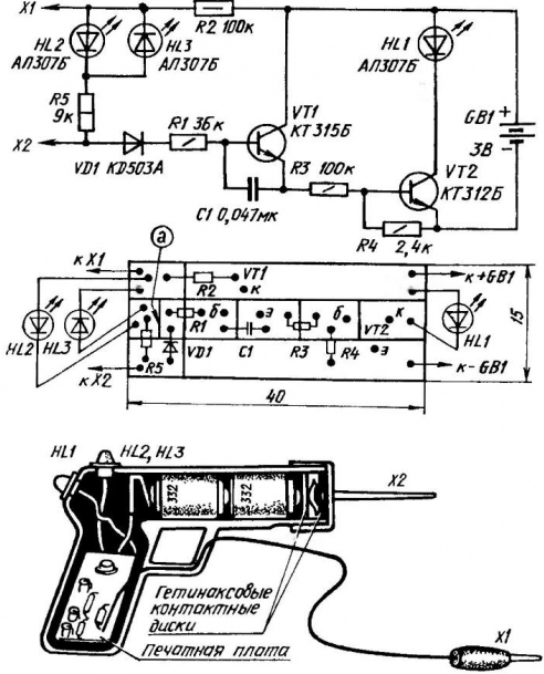
Primitive "control print" - electroputere with two wires and a bulb - far not the best device for the "continuity" of the electrical circuits. Produced industry testers and avometr is also called a gift, especially when dealing with modern appliances, and they are not cheap. Here and electricians have the chance to create a probe-indicators - universal, compact and reliable.
Make yourself this probe, designed, incidentally, talented representative of the rural hinterland, at first could not get enough. The device really is a reliable assistant lineman, allowing you not only to test the electric circuit, but separate, elements - diodes, transistors, capacitors, resistors. Assembled in the housing of the toy gun and equipped with a stylus, he also makes it possible to control AC and DC voltage from 1 up to 400 V, to detect the phase and zero wire network, to assess the resistance isolation of electrical equipment.
However, over time there has been a discrepancy between the real opportunities probe indicator and the requirements for such devices continuously evolving elektroradiotekhnika. In particular, ceased to hold the complexity of the detection voltage in DC circuits and clarifying indicates whether extinguished alarm led on the wired obestocheno line or a short circuit. Therefore, the device had to be upgraded. The changes are minimal (details НL2, НL3, R5 and section "a" on the circuit the Board), but the universal probe-indicator now again in business.
As before, the basis of the device - a DC amplifier transistors VT1 - VT2, which loading is led НL1. Resistors R1 and R3 limit IB semiconductor triodes. Capacitor C1 creates a negative feedback circuit connection, AC-coupled, eliminating false indication from external noise. R4 resistor in the base circuit of VT2 is used to set the required limit of measurement resistances. Resistor R2 limits the I edited while working probe in chains AC and DC currents. The VD1 diode performs the function of half-wave rectifier. LEDs НL2 and НL3 are indicators of polarity, the current through which limits the resistor R5.

A circuit diagram, the circuit Board topology and layout the upgraded probe
In the initial state, the transistors are closed and the indicator НL1 not lit. But if the probes connect to each other or to connect them to a working de-energized circuit, having Rц not more than 500 ohms, НL1 lit. The brightness of its light back proportional to the resistance of the circuit under test.
When connecting the probe to the circuit of the alternating current of the positive half open the transistors and the led НL1 lights up. Glow and more indicators НL2 and НL3 at the input device. If the voltage is constant, and НL1 НL3 will be lit when the probe x2 will be a plus (when other polarity of the voltage in check the chain they will go out, but the led lights up НL2).
As when working with the device before the upgrade, faulty diodes and transistors check by comparison of the p-n transitions. The indicates cliff, but if NEITHER is lit constantly, the test transition test.
When connected to the probe defective capacitor HL1 led flashes and then turns off. Brightness and flash duration are dependent on the audited electric capacity. When the capacitor is broken or has a large leak, the led is permanently illuminated.
"Phase" is determined as follows: probe X1 we take in hand, and a stylus touch x2 the studied wires. If HL1 led is lit, "phase", that is, there is.
Methods other checks have not changed, but upgraded to work probe-indicator still easier and faster than before, because the role of the informants are three led indicator.
Author: B. Turner


