


")

The article describes the design of the indicator that shows which way and how deviated the value of the controlled parameter. In the device provided the output signal, which includes the actuator. The indicator may to be easily reconfigured for use in gauge mode the signal level.
The led indicator is designed to monitor the deviation of the signal direct current from the set value in the positive or negative side. Collected on six LEDs described variant of the device shows three gradation deviation from zero in each direction. The maximum value the detected deviation is +0.1 V. the voltage at the inputs must not exceed 3 In otherwise would require the use of the input attenuator. Input resistance indicator - about 6 ohms.
This indicator is a part of automatic maintenance of the set soil moisture [1] and is used to monitor the deviation from the optimal values.
The display of the device is a line of six LEDs located either horizontally or vertically. In the absence of a reject signal from given three values of right (or upper) led in the line don't Shine, three the rest included. If a positive deviation of the signal number included LEDs increases proportionately, for negative values decreases.
The indicator is powered stable bipolar voltage 2x12; current consumption is 40 mA.
Scheme of the indicator shown in Fig. 1. Controlled input served on input A. input B sum exemplary voltage. It should be highly stable. It is set equal to the nominal value of the controlled voltage.
Oh DA1 connected in the circuit with parallel negative OS. Such inclusion AW rarely used because of the presence of common-mode voltage at the output, but for indicator it is quite acceptable. Common-mode voltage offset when establishing device.
The output of op-amp included bipolar emitter-follower transistors VT1, VT2, the output of which through a threshold device (Schmitt trigger) operated irrigation valve system to maintain soil moisture. If the device is to be used only as an indicator, the emitter follower can to exclude.
The amplified current signal through the resistor R5 is supplied to the circuit of the diodes VD1-VD5, role stabistors. The voltage drop across each diode is about 0.6 V, also define "height" steps indication. The distribution of voltage in a circuit diodes depends on the ratio of resistance values of the resistors R7 and R8 and the level the output signal OS.
In the initial state at the point of connection of diodes VD3 and VD4 must be zero voltage relative to the common wire. The base of transistor VT3-VT5 are under positive voltage, so the transistor VT3-VT5, and hence VT10-VT12 open. LEDs HL1-HL3 de-energized, as they shunted open transistor VT12.
To the base of transistor VT7, VT8 applied negative voltage, and VТ6 - zero, so they closed; closed the transistor VT13-VT15. Through the transistor VT12 and LEDs HL4 - HL6 flows operating current - LEDs included.
With the increase of the input voltage And the output voltage Oh decreases, the point zero voltage moves to the left through the chain of diodes VD1 - VD5. Consistently close pairs of transistors VT5 and VT12, VT4 and VT11, VT3 and VT10, stopping the shunt LEDs HL3, HL2 and HL1, respectively. Therefore, LEDs are included one after the other.
When the voltage drops at the inlet And the point of zero potential moves right through the chain of diodes, open a pair of transistors VT6 and VT13, VT7 and VT14, VT8 and VT15. LEDs HL4, HL5 and HL6 one by one extinguished.
The LEDs in the indicator series. The current through them is supported constant and equal to 10 mA current stabilizer transistor VT9. This reduces the load on the PSU and makes it permanent. To manage each led you have to use a couple of transistors as gain a single transistor is not enough.
In the magazine "Radio" were published similar led level meters signal [2-5]. Some of their schematics used in the described device. It differs by the presence of differential inputs, and higher adjustable gain, and a serial connection LEDs to a power source that extends the application possibilities.
All the details of the indicator, except the LEDs are mounted on a single side printed circuit Board thickness of 1 mm from the foil fiberglass. The drawing Board is shown in Fig. 2. The fee is made by means of cutting with a ruler torch, turned on tochile. Black lines on the drawing Board are areas where the foil is cut. Of course, cost can be performed using conventional etching.
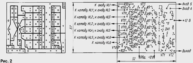
Diodes and most of the resistors on the Board set to "upright". LEDs mounted on the front panel and with the Board connected to the wiring conductors.
The transistors used in the indicator can be any low-power silicon. For example, instead KT315B (VT3-VT8) will fit the old type transistors MP (ratio h21e>45), and instead KTV (VT10 - VT15) - MP (h21e>20). However, this will slightly increase the size of the circuit Board. Transistors VT1, VT2, VT9 must allow the voltage at the collector not less than 30 V.
Diodes VD1-VD5 - any low-power silicon. Application OS CUT non-critical - the indicator can work with another OS, designed for a voltage 2x15 Q. Can I change the number of LEDs, respectively, and pairs of governors transistors.
Establishing indicator starting with the initial installation status LEDs. For this inputs A and B to be interconnected and serve them exemplary voltage. It is usually formed from the power supply through additional stabilizer and a resistive divider (not shown). Empirically on the circuit of the diodes VD1-VD5 find the optimal point to which is connected the right circuit output resistor R5. The selection criterion of the optimal point - LEDs HL4-HL6 Shine but HL1-HL3 - off.
Then disconnect the input and feed on him stable voltage that can be be adjusted up to +1…2 In the value model. The source of this voltage can serve as another of the same divider, but with a variable resistor in one of the shoulders. Set the input a voltage exactly equal to the exemplary, and choose a resistor R8 at which to turn on the next led you want to increase the voltage as much as you need to reduce so, conversely, to turn off one of them. From the thoroughness of the implementation this operation will depend on the accuracy of the indication of "zero".
The required sensitivity of the indicator set by selection of resistor R3 in circuit negative OS OS.
If you need to use the indicator in the measurement mode of signal inputs A and B to establish a connect with the common wire and connect a resistor R5 to the point circuit of the diodes VD1 - VD5, which gives the minimum number of LEDs included. Then choose the resistor R8 so that the led HL6 was on the border of the beginning glow. Then input B left connected to the common wire, and the input And served measured switching voltage. When the input signal of the opposite the polarity of the inputs are interchanged. The sensitivity of the indicator change selection resistor R3. If the level of the input signal In reaches 3, you can do without operational amplifier and emitter follower. In this case, the source signal with an internal resistance of 2 ohms is connected to a circuit of diodes VD1-VD5 through the resistor R5.
Literature
Author: Y. Egorov, Moscow