


")

The proposed device, the led indicators (see figure) allows a sufficient degree of accuracy to show the voltage on the power source, consisting of two batteries or battery cells.
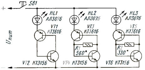
On fully charged batteries, the battery voltage is 2.4 V (for a "fresh" battery cells 3 In). In this case, all three are lit led. With a smooth decrease of the voltage to 2.3 In first goes out HL3, and then at a voltage of 2 In 15 turns off HL2. With the further decrease of the voltage to 2 will go out In HL1. This indicates complete discharge of the batteries and need for replacement or recharging.
When using galvanic cells the switching thresholds must be set to the voltage of 2.45 and 2.7 respectively In the ignition Threshold LEDs HL2 and HL3 is determined by the resistances of resistors R1 and R2
The principle of operation of the indicator cells based on the use of properties avalanche switching transistors in dintorni the switching circuit. To achieve a certain voltage (the voltage of opening) transistors are closed and the current through them is negligible. When the voltage exceeds the specified, the avalanche transistors are opened, the current increases and the voltage across the transistor drops to 0.5 to 0.8 V. When the voltage decreases the current, and when you reduce it to less than the holding current of the transistors closed. This property can be used to control any device. For example, to disable player or enable audible alarm when a voltage reduction on battery below admissible.
The resistor introduces a scheme of the cell negative feedback current. Change the resistance of a resistor you can adjust the threshold voltage of the opening and the closure of the transistors. If the resistance of the resistor is zero (i.e. the jumper is installed), then the p-n junctions, the base-emitter of transistors equivalent conventional diode.
In this device it is desirable to use integrated circuit assemblies. It because of the change in temperature within wide limits change the parameters of transistors that can affect the accuracy of the indication. Allowed the use of discrete series transistors KT315, KT361, KT3102, CT. All the transistors must have a current transfer ratio base 80. LEDs you can use any of the series AL307.
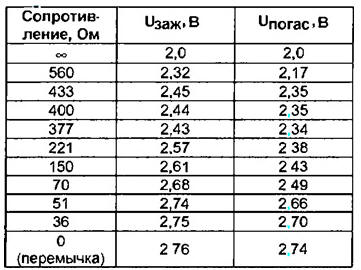
For transistors with a transmission coefficient of about 80 of the resistors obtained experimentally, are given in the table.
The disadvantage of this device is a small hysteresis on and off indicator cells. Indicating instrument is sensitive to excess supply voltage. When the device is connected to the points with a voltage, exceeding the voltage indicator, the possible failure of the LEDs. Install the resistor in series with the led reduces brightness. For devices with Autonomous power supply important efficiency indicator. So you need to turn the power on indicator short press the SB1.
When you configure the device instead of the resistors R1 and R2 should be set trimmer resistors to set the thresholds display. After that it is necessary to measure the obtained values of the resistance and to establish permanent resistors of the same resistance.
Author: E. Marushchak, Yuzhnoukrainsk, Ukraine