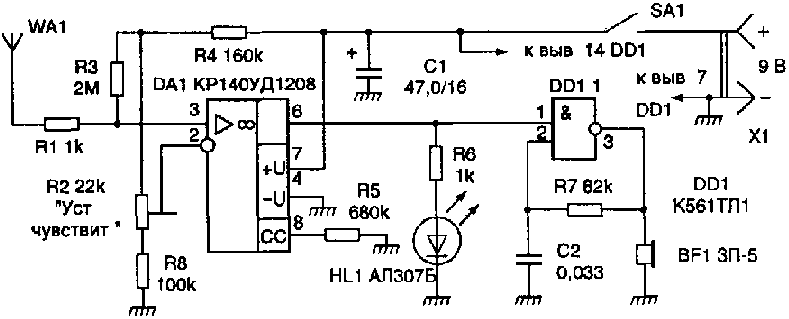
Scheme indicator hidden wiring is shown in Fig. 1. It consists of two node of the amplifier of the AC voltage, which is based on Micropower operational amplifier DA1, and the generator of sound vibrations frequency collected inverting Schmitt trigger DD1.1 chip CTL, castorocauda chain R7C2 and the piezo oscillator BF1.
When the location of the antenna WA1 near current-carrying wires tip EMF of industrial frequency of 50 Hz is amplified chip DA1, the resulting HL1 led is lit. It's output voltage operational amplifier, pulsed with a frequency of 50 Hz, launches the generator of sound frequency.
The current consumed by the circuits of the device when feeding them from the source voltage of 9 V, not exceeding 2 mA, and at the inclusion of led HL1 - b...7 mA. The power source can be battery 7 D-0,125, Corundum or similar foreign production.
Sometimes, especially when the required wiring perched, watching the light HL1 and difficult enough audible alarm. In this case, the led may to be disabled, which will increase the efficiency of the device. All fixed resistors - MLT-0,125, adjusted R2 resistor - type GPA-38B, the capacitor C1 is K50-6. Antenna WA1 is the ground foil on the Board about the size of H mm.

The circuit Board is placed in a housing made of dielectric material so that the antenna was in the head part and was the most removed from the hands of the operator. On the front side of the housing feature the power switch SA1, led HL1 and the BF1 sound projector. Initial the sensitivity of the device set a trimming resistor R2. Unmistakably the mounted device in the establishment does not need.
Publication: www.cxem.net


