


")

It is well known how dangerous it is for three-phase motor loss voltage in one of the phases. Only an experienced forces in a timely manner notice that with the change in sound as the engine often continues to work but quickly overheats and burns out. In production use special the protective device that automatically turns off the motor in case of phase voltage. However, for domestic use such devices unnecessarily expensive. To prevent accident will help the proposed indicator signaling failure is not only light but also sound.
Basic health indicators of a three-phase network can serve in neon the lamp is connected through damping resistors between each phase conductor and neutral.
Since a person's attention is absorbed, as a rule, the work being performed, extinguished the lamp it may be time and not notice. To attract attention to emergency situation the audio signal. Besides the neon lights sometimes randomly blink, so for signaling is better to use LEDs.
The scheme developed indicator is presented in Fig. 1.
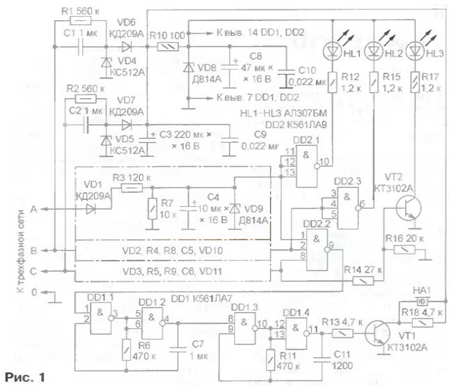
The presence of voltage in each phase control using three identical detectors. For example, the phase detector And consists of a diode VD1, resistor divider R3R7, the smoothing capacitor C4 and limiting the rectified the voltage of the Zener diode VD9. With proper phase, the voltage level at the output detector corresponds to the log. 1, when the defective - log. 0.
When fully operational the network log. 1 are present at all inputs of the element DD2.2 and log. 0 at its output blocks the tone generator on the chip DD1. The elements DD2.1 and DD2.3 control the LEDs HL1 and HL2, whose illumination indicates the presence of voltage respectively in phases A and B. the Indicator phase - HL3 led - controls the key on the transistor VT2. So not adding another chip.
In the event of failure of one of the phases will turn off the corresponding led, the log. 0 at the output of the element DD2.2 changes to the log. 1 and the generator on the elements DD1.1, DD1.2 will begin to produce a pulse frequency of 2…3 Hz, which will be periodically to enable the audio frequency generator on the elements DD1.3, DD1.4. As a result of piezoceramic emitter HA1 will hear an intermittent beep.
The indicator feed two identical rectifier (C1. R1. VD4 and C2. R2, VD5), inputs which are connected to different phases of the network, in this case, b and C. Thanks diodes VD6 and VD7 the device is actually nurtures the rectier, the output the voltage a bit more. But if a fault occurs in one phase power proceeds from the other, the indicator keeps working. Voltage the supply of chips is additionally stabilized by the Zener diode VD8.
The indicator is assembled on a printed circuit Board shown in Fig. 2.

Resistors R1-R5-MLT-0,5. Less powerful here is not recommended by reasons of electrical safety. Resistors R10 and R17 - MLT-0,125, the rest size 1206 surface-mount (PM). Oxide capacitors - K50-35 or similar to the voltage of at least 16 V. the Capacitors C1, C2 - K73-17 the voltage of at least 250 V, C7 - K10-17, all other ceramic size 1206 PM. All the elements for a PM (resistors and capacitors) are mounted from the side traces, pripaivaya directly to the pads.
Instead of chips series C can be set (without schema changes) functional analogues from C or imported chip CMOS structure. Transistors CTA can be replaced by others of the same series or series KT315, CT. As Zener VD8-VD11 you can use any voltage stabilization 7…9 V (for example, XA, D with any index), but it should not VD8 to be less than VD9 VD11. Zener diodes VD4, VD5 replace on other voltage 10… 15 V, for example, KSA. Diodes KDA can be replaced by KD105B or KD102B. As LEDs HL1-HL3 any suitable, preferably elevated brightness. HA1 - - piezoelectric sound emitter SN-1 or similar.
Correctly assembled the indicator in establishing and starts to work immediately after turning on. You can change the frequency of the sound signal, selecting the value of the resistor R11 or capacitor C11.
Author: I. Korotkov, village of Bucha, Kyiv region, Ukraine