A simple but sensitive device responds to the electric field wires and cables for various purposes, including high-voltage lines power and signal field intensity is above a certain level. The device may be used to alert the people working near electrical installations, about the danger of electric shock. In private life he useful as sequence lead, and to detect hidden wiring.
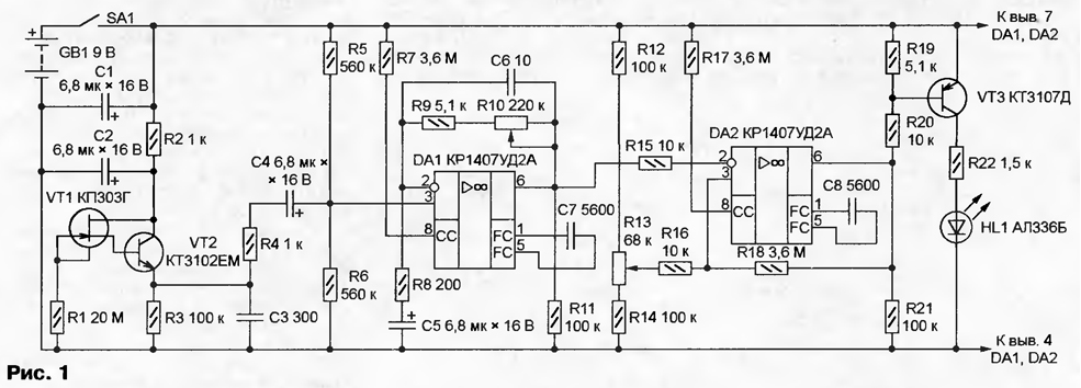
The proposed indicator electric fields (PEF) is easy to use, equipped with adjustments of sensitivity and threshold. The IEP scheme is shown in Fig. 1.

(click to enlarge)
Sensitive element is a field-effect transistor VT1, United the shutter and the housing of which is induced by a signal proportional to the field strength. High-ohmic resistor R1 prevents the accumulation of static charges. After through the emitter follower transistor VT2, the induced signal is allocated to the resistor R3. The capacitor C3 suppresses high-frequency pulses and interference. Through resistor R4 and capacitor C4 signal is supplied to the non-inverting input of op-amp DA1. Resistors R5, R6 create an artificial zero point, a, R7 and R11 are used to set the appropriate operation mode OS. Variable resistor R10 regulate the gain of the stage. Capacitors C6 and C7 - correction elements frequency features OS.
Oh DA2 compares the voltage received through a resistor R15 to the output of DA1, exemplary. Last regulate a variable resistor R13. Appointment resistors R17 and R21 similarly, R7 and R11. Positive feedback, thanks through a resistor R18 to the comparator at the shelter DA2 has a small hysteresis that increase the clarity of operation. The output signal of the comparator via the key on the VT3 transistor drives the led HL1.
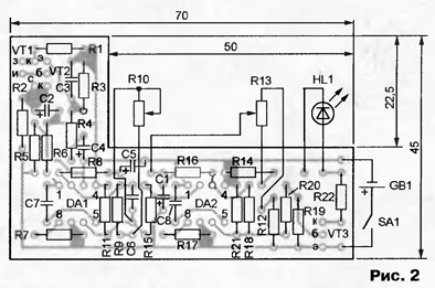
PCB IEP (Fig. 2) of one-sided foil fiberglass placed in a plastic housing dimensions 90x60x22 mm.

The neck Board is designed for placing beside it the battery GB1 voltage of 9 V ("Krona", "Emery"). Controls (R10, R13, SA1) and led HL1 displayed on one of the side walls of the housing. Performance the IEP is saved by reducing supply voltage to 3 V. In standby mode the current consumption does not exceed 0.2 mA, increasing to 5 mA when activated and the ignition of the led. When establishing the IEP may need to pick up the resistors R9 and R18.
Transistor VT1 can be replaced by any of the series 303, and VT2 and VT3 - low-power silicon bipolar transistors of the corresponding structure. Variables resistors R10 and R13 - GPA-4. The switch SA1 - PT-1-1B.
If the slider of the variable resistor R10 is set in the left, and R13 is at the top the diagram position, the gain induced on the sensor the IEP of the signal is minimal, and the threshold the maximum response. In this state the device by the ignition LEDs HL1 to distinguish between "phase" wire household power from "zero". Enough turn to bring the sensor - the body of the transistor VT1 to isolation each of these wires. It is unacceptable to touch an uninsulated sensor wires or metal objects, for example, the housings of the apparatus.
To find using the IEP hidden in the wall wiring, it is necessary to increase gain and to lower the threshold. The approach of the sensor wires to the track, which is under stress, evidenced by the ignition of the led HL1. Further the gain is increased and the lowering of the threshold detect current-carrying wire at a considerable distance. For example, customized accordingly the IEP the signal at a distance of 3 m from the tyre, which is under a voltage of 10 kV.
Author: B. Sokolov, Protvino, Moscow region.


