


")

This indicator responds to the total flux of ionizing gamma, beta and alpha radiation and, in spite of extraordinary simplicity, is quite reliable in operation.
Circuit indicator consists of the Converter voltage and the node, measurements. The voltage Converter is assembled but the key scheme, a switching inductance L1 in the DC current by rectifying and filtering the emerging EMF.
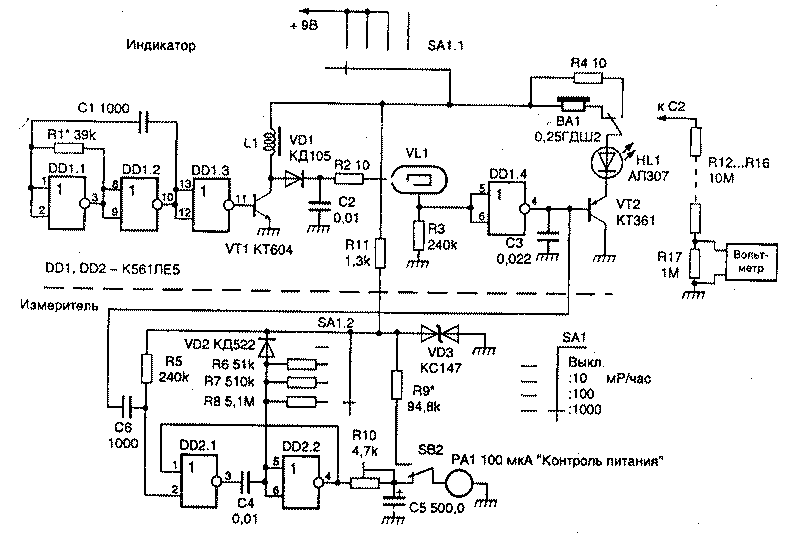
A master oscillator with a frequency of about 700 Hz assembled on the elements DD1.1, DD1.2. Since the generated pulses are asymmetric, it is possible to improve the efficiency in use, after inverting, shorter negative half wave of momentum. Rectified by the diode VD1 and filtered by capacitor C2 voltage (around 380) via a load resistor is applied to the ionizing radiation counter Geiger-Muller VL1. It should be noted that the output voltage of the Converter, due to the instability of the power source, has little effect on measurement accuracy. In this case, for the counter type STS-5 changing the input voltage may be about 90 V.
Appearing at the resistor R3 is short positive pulses through a buffer inverter DD1.4 served on emittedby repeater VT2. Capacitor C3 serves to suppress interference from the generator-voltage Converter. Load repeater is the dynamic head of BA1 and led HL1. The amplitude of the current pulse through the led and the head is determined by the internal resistance of the power source and the resistance of the collector-emitter of the transistor VT2. And since the control pulses of the element is very short, the average supply unit current at the natural background radiation is determined only by the current drawn by the voltage Converter.
When the level of radiation to 0.1 Mr/h (and thus increasing the frequency of pulses), the average current consumption increases, therefore, for greater efficiency dynamic head switch SB1 can be disabled.
The node measuring the level of radioactivity is a simple analog frequency meter, assembled on the elements DD2.1, DD2.2. Indicator is microammeter RA1. Node circuit includes a standby multivibrator controlled by pulses from the inverter DD1.4. The accuracy of measurements is provided by a power supply from a parametric stabilizer VD3R11. Button SB2 is used to switch microammeter PA control voltage through the quenching resistor R10. The outside measurements are switched by the switch SA1.2 by the switching timing resistors R6-R8.
The indicator can be assembled as with the measurement scheme, and without it. In the latter case excludes the elements DD2.1, DD2.2, PA1. If you use small details, and to determine the level of radioactivity to leave only the led, the indicator will not exceed two dimensions battery type "Crown" Counter VL1 can be replaced by SBM-10, SBM-20, SBM-21, STS, etc. the Transistor VT1 - CT, the transistor VT2 - any low-power silicon corresponding structure. The measuring head RA1 type M with the current total deviation of 100 µa (but can be any other current full deflection of not more than 300 μa). Coil L1 is wound on two stacked ferrite rings MNM size CHH and contains 200 turns of wire PELSHO 0.26 mm, an inductance of about 240 mg.
Establishing indicator easy. First of all, you need to collect the input divider voltmeter to measure high voltage . Since the output current of the voltage Converter is very small, used a voltmeter should have an input impedance of at least 10 MW.
Connecting the divider to the capacitor C2, the change of the resistance of the resistor R1 for setting the output voltage of about 380…400 V. If the device is used as an indicator, the configuration ends here.
When using the indicator as a measuring device, it is necessary to calibrate the arrow head. You can go from the fact that the dependence of the number of pulses at the output of the Geiger-Muller from the level of radioactivity linear. If precise timing resistance of resistors R6-R8, it is possible to calibrate the indicator can only be in one point of the scale. This is done so. Placing the light next to the sensor model of the factory unit, determine the background level in the area. Let's say he is 0.003 Mr/HR. The change of the resistance of the tuning resistor R8 set the arrow PA1 per division "30" (at the scale -100 μa). This calibration is complete. However, it must take into account one thing. Because of the presence of the counter own background, the latter may introduce error in the calibration on the range 0…0.1 Mr/h. Therefore, if possible, calibration is best done at elevated background levels, but in the first case, the accuracy of the indicator of the meter will be sufficient for practical measurements. Instead of turning trimpot resistor R10, while pressing the button SB2 adjust the microammeter to a value corresponding to the voltage, and replace the resistor at a constant. This establishment ends.
Publication: N. Bolshakov, rf.atnn.ru