


")

When creating indicators field strength arises the problem of dynamic range - it is difficult to manufacture a device that would allow control and strong and weak signals. The problem is simplified if we apply a logarithmic the amplifier, as did the author of the present article.
To search for sources of radio signals or interference, and also when setting up and checking antenna technology applied field strength indicators. The usual requirements, requirements for these devices are large ranges of operating frequencies and the displayed signal level, efficiency and small size. All of these requirements you can implement, if you apply a specialized chip. Example serve chips logarithmic amplifiers-detectors of the firm ANALOG DEVICES - AD606, AD8306, AD8307, etc.
Below is a brief description of the AD8307 chip and design based on it. In the composition of this chip is shestibalny (14,3 dB amplification cascade) the amplifier-limiter with the detecting circuits and other auxiliary nodes.
The main parameters
- Operating frequency range, MHz......0…500
- The range of variation of the voltage of the input signal, dB......92
- The steepness of the output voltage (when the nonlinearity is not more than 1 dB mV/dB......25
- Power supply voltage (single polar), ......2,7…5,5
- Current consumption, mA......7…8
- Power spectral density of noise, NV/vГц......1,5
- Input resistance, kOhm......1,1
- Input capacitance, PF......1,4
Diagram of the field strength on the chip shown in Fig. 1.
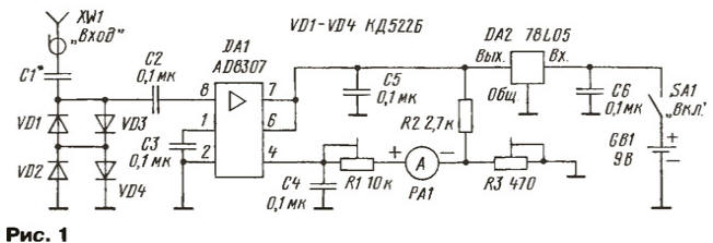
Pins 1 and 8 DA1 is a differential input, when using only one them through the second capacitor element is connected to the common wire. Pin 4 - this output, when the input signal on this output is present a voltage of about 0.2…0.25 V, and the output impedance is about 12 com. When the input signal is the output voltage increases by 25 mV at the increase in the input signal by 1 dB.
Operating frequency range is limited from below by the capacitors C1 and C2, top - frequency properties of a chip of DA1 and is approximately 500 MHz, at the reduction of sensitivity at 20 dB to about 900 MHz. As an indicator applied pointer instrument - ammeter PA1. The input diodes installed VD1-VD4, which protect the chip from the powerful signals and interference. To the exit the chips through a trimming resistor R1 connected to the positive output of the analogue device, and the negative voltage with the trimpot resistor R3. It done to ensure that in the absence of a signal the meter pointer was installed to zero.
DA1 chip is powered by an integrated voltage regulator on the chip DA2. Enable devices to perform the switch SA1. Current consumption is 11 …12 mA.
As an antenna it is convenient to use the telescopic antenna length of several tens of centimeters. The input impedance of the device is several hundreds of ohms, so matching indicator with 50 or 75 Ohm lines or antennas at the entrance must be set by a resistor 51 or 82 Ohms respectively.
Capacitor C1 is selected depending on the desired sensitivity and range operating frequencies. Its capacity can range from a few to a few hundred PF.
Most parts are on the PCB of bilateral foil fiberglass thickness of 1… 1.5 mm, a sketch of which is shown in Fig. 2.
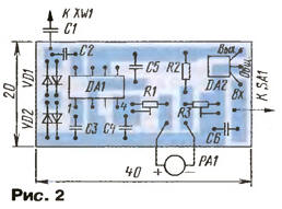
Second metalized side is used as the screen and are connected to a common the first side wire in several places. The fee together with the microammeter housed in a metal case with lid. In the upper part installed coaxial socket XW1 and the printed circuit Board, which should be soldered on to the edge the body. Microammeter RA1 installed on the side wall.
If the device is to be powered from the battery, to charge it you need to provide a small-sized socket. This charger must have galvanic isolation from the mains.
In the device you can apply details: chip DA2 - CREA, CREB, microammeter RA1 - M with the current total deviation of 100 μa. Nest XW1 - small-sized high frequency of any type, for example, SMA. Rigged resistors - SDR-19, constant - MLT, S2-33, P1-4. Capacitors C2- C6 - K10-17, preferably C1 to apply a working voltage of 300 V or more (K73), this will increase the safety of use of the indicator. The fact is that when finding sources of radio emission is probable that touch the antenna conductors connected to the network.
Establishing device is simple. Resistor R3 sets the arrow microammeter to the zero mark when there is no signal. Then fed to the input of The RF signal has a frequency of about 100 MHz and a voltage of 1 V. Trimmer R1 set the arrow of the microammeter on the ' 100 ' mark.
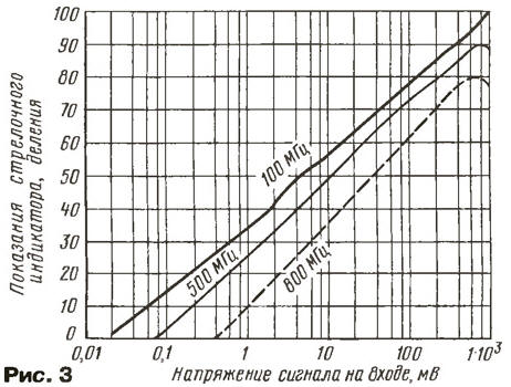
Experimentally taken of the characteristics of the indicator shown in Fig. 3. They show that at frequencies less than 100 MHz, the indicator starts to respond to signals with voltage 20…30 mV and the dynamic range displayed voltage is 92 to 95 dB. At a frequency of 500 MHz, the sensitivity drops to 80…100 mV and at a frequency of 900 MHz it drops to 500…600 mV. After carrying out the adjustment it is necessary to remove this dependency, to build it in the form schedule and post it on meter body.
If this device be used in conjunction with interchangeable bandpass filters, it can be used for configuration or orientation of television antennas on the maximum of the received signal.
Author: I. Nechaev (UA3WIA), Kursk