In recent years, many respected European publishers pay considerable attention to various technical devices used in the search operations. Every year on the shelves of bookstores do new books with descriptions of the various devices. Admittedly, mostly these devices are complex in the Assembly and regulation and are unlikely to be recommended to repeat novice Amateurs.
However, in one of the books published in the series "Elektronicke hledace" popular European publisher "BEN", the author recently not without surprise, found a diagram of the detector, which seemed very familiar. The main element with which this device is analyzed the presence of metal objects is quartz. The results of the analysis evaluated both visually and aurally.
Schematic diagram
We offer our readers the design represents one of the options metal detectors of the type FM (Frequency Meter), then there is a device in based on the principle analysis of the frequency deviation of the reference oscillator under the influence of metallic objects caught in the area of the search coil.
A careful study of the schematic you can see that this the device is an improved version of the detector, discussed in the previous section. One of the main distinguishing features this design remains the analyzer made on quartz the element Q1. In addition, in an improved version of the detector in as an indicator in addition to a pointer device plan applied acoustic alarm.
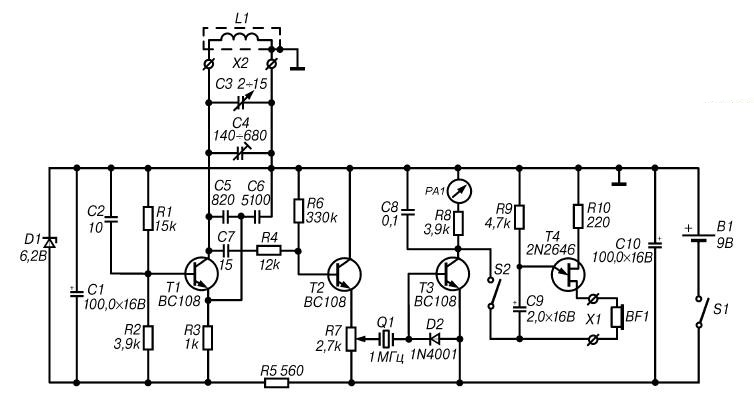
Since in the proposed scheme (Fig. 2.16) renumbered items, uses a new element base and added additional cascade, the author felt it necessary to examine in more detail its features.

Fig. 2.16. A schematic diagram of an improved detector with quartz
As in the previous design, the basis of the scheme of this detector are the measuring generator, buffer amp, detector of fluctuations in the RF analyzer and indicating instrument.
The oscillating circuit of the generator of high frequency, performed on the transistor T1. consists of a coil L1 and capacitors C3-C6. The working frequency of the RF generator depends on the deviation of the inductance of the search coil L1, and the change of containers trimmer capacitor C4 and the adjusting capacitor C3. In the absence of near the coil L1 of metal objects, the frequency of oscillations excited in The RF generator must be equal to the frequency of the quartz element Q1, that is, in this case 1 MHz.
Once in range of the search coil L1 will be metal the subject, its inductance will change. This will result in a change in the oscillation frequency RF generator. Further, the RF signal is fed to the buffer cascade, providing coordination of generator with the subsequent circuits. As a buffer stage use the emitter follower is performed on the transistor T2.
From the output emitter repeater RF signal through a regulating resistor R7 and quartz Q1 is supplied to the detector made the diode D2. Due to high the quality factor of the quartz slightest change in frequency of the measuring oscillator will be to reduce the impedance of the quartz element. As a result to the input of the DC amplifier (the base of transistor T3) is supplied the low-frequency signal, the amplitude of which provides a corresponding the deflection of the indicator device.
Load UPT performed on the transistor T3, is a pointer instrument with current full deflection of 1 mA. With the closure of the switch S2 to the load circuit the generator of the sound signal is performed on the transistor T4.
Food metal detector is from the source B1 voltage of 9 V.
Details and design
As discussed earlier in some designs, for the manufacture metal detector with quartz element, you can use any development Board. So used to detail without facing any restrictions associated with dimensions. The installation can be both mounted and print.
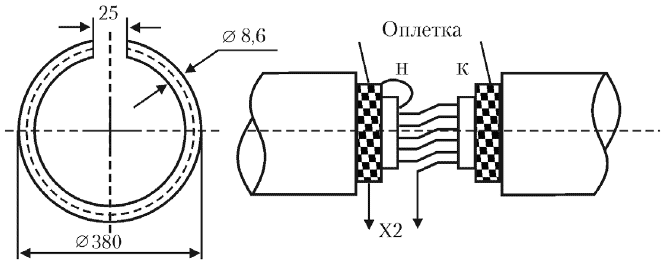
The search coil L1 (Fig. 2.17) is similar to the coil used in the detector, which was discussed in the previous section.
Instead of BC108 transistors type indicated in the diagram, in this design it is possible to use virtually any domestic low-power silicon transistors for example, type KT315B. Instead of the diode type part no 1n4001 (D2) is recommended any germanium diode series or D2 D9 with any letter index.

Fig. 2.17. The design of the coil L1
As element Q1, you can use any of the quartz element frequency at kHz to 1.1 MHz. Power source B1 can serve as a battery "Krona" or two batteries 3336L, are connected in series.
Board with the controls it contains and the power source are placed in any a suitable plastic or wooden case. On the housing cover set variable resistor R7, the switches S1 and S2, connectors X1 and x2, and also, the indicator PA1.
The search coil L1 should be installed on the end of a suitable handle length 100-120 see Connecting the coil with the Board device is shielded stranded cable.
Establishing
The main condition for ensuring quality setting for this device is the lack of large metal objects at a distance of not less than 1.5 m from the search coil L1.
Direct the establishment of the detector should start with the desired the oscillation frequency generated by an RF generator. The oscillation frequency of the RF should be equal to the frequency of the quartz element Q1. To perform this adjustment it is recommended to use a digital frequency meter. In this case, the frequency value first roughly set by changing the capacitance of the capacitor C4, and then accurately - adjustment of the capacitor C3.
In the absence of frequency-tuning RF generator may be indications indicator PA1. Quartz Q1 is an element of connection between the measuring and flat parts of the device, therefore, the resistance at the time of resonance great. Thus, the exact configuration of oscillation of an RF generator frequency quartz will testify to the minimum reading of the pointer device PA1.
The sensitivity of this device is governed by the resistor R7.
The order of work
In the practical use of this detector should be variable resistor R7 to set the arrow indicator PA1 to zero. When this to some extent compensates for the change of operation modes, due to battery discharge, the change in the ambient temperature or the deviation of the magnetic properties of the soil.
If in the process of work in the area of the search coil L1 will be any a metallic object, the meter needle PA1 deviates. In this case, when the closure of the contacts of the switch S2 in the head phones there is the sound signal.
Author: M. V. Adamenko


