


")

I developed the metal detector has not been used neither in peace operations to identify and neutralize minefields, nor in large-scale geological or archaeological surveys. Designed not for professionals but those whose desire to "look under the earth" is able to satisfy design with the parameters given in the table, it is a improved version "of the metal detector on the beat".
The sensitivity of the device is enhanced through beneficial use (clear fixation) according to the duration of the probe pulse intensity from themselves parcels with the introduction of the search oscillator automatic frequency control (AFC). Moreover, additional measures to stabilize the voltage and temperature compensation of electronic components is not required.
As predicted by skeptics "irreconcilable differences" (say, a change in the frequency do search oscillatory circuit in contact with the metal in the work zone associated with normal operation of the system control allowed myself practice. It turned out that when moving the sensor above the investigated surface with a rate of 0.5 - 1 m/s diagram of the device is not in conflict with - locked loop frequency with a significant lag (large constant time).
Already from the analysis of the block diagram shows that to produce such a device is obviously harder than any of the former is less sensitive counterparts, including metal detectors, published at No. 8’85 and 4'96 magazine "modelist-constructor". Because my proposed design, in addition to the standard set of exemplary quartz (1) and measurement (2) generators, external inductors I. (the search frame sensor), the mixer (3) Registrar and sound WA (telephone earpiece) - there is a new, significantly improved operational characteristics of the device. This integrator (4), generating a sawtooth a signal with amplitude proportional to the control beat frequency, and the driver of the write pulse (5), which together with the key (6) and source repeater VT represent an analog storage device, fixing the peak voltage from the integrator.
No cost, metal detector without comparator (7), providing automatic transfer the electronics from the zone of maximum sensitivity in the registration area beat one-to-one (and Vice versa), without special generator VCO (8), converts the voltage generated in the source follower, electric oscillations of a frequency 200-8000 Hz, and without the above-mentioned original system-locked loop frequency control (9) with a special node that slow the response of the device to an overly abrupt change of the control voltage. There here and a number of other technical solutions, among which, of course, can not highlight "operazioni" and Spetsstal (10).
The main parameters of the detector
- The dimensions of the printed PCB, mm................... 90x70x2
- Voltage power................ 9
- Consumed device current, mA.............. 6
Depth of detection of steel items in black soil with well-established dry weather, mm
- a) disk 10x2 mm..............100
- b) Disk 100x20 mm.............680
- in disk 500x100 mm (manhole)........1400
In practice, such devices when the selected method audible signal sounds allows you to listen to both frequencies at the same time, significantly facilitating the initial set up of the device on a specific sensitivity. And the reliability is quite high. Even in the extreme situation, when, for example, a search frame-sensor approaches massive metal object at the distance at which the difference frequency becomes almost critical (70 Hz), the malfunction does not occur in head the phone could hear the changing beat frequency.
Now about the particulars reflected on the electrical circuit scheme. Exemplary generator is made on an element DD1.1. Its frequency stable quartz resonator ZQ1 in the circuit positive feedback. To ensure the excitation of the generator during power serves as the resistor R1. Available here the buffer element DD1.2 unloads generator, and generates a signal with digital levels. The resistor R2 determines the degree of load and the maximum power dissipated in the quartz resonator.
This generator can work with almost any resonators at a current consumption 500-800 mA. And to those who followed the frequency divider by two (element DD2.1) generates a signal with a symmetrical square wave required for normal operation mixer.
Measuring the generator is assembled according to the scheme asymmetrical multivibrator (transistors VT1 and VT2). Finding the mode of self-excitation circuit provides positive feedback on the capacitor C7. Customizability elements serve NW - C5, VD1 and the search coil sensor L1. Moreover, the generation of is in the range from 500 kHz to 700 kHz, depending on the available quartz resonator.
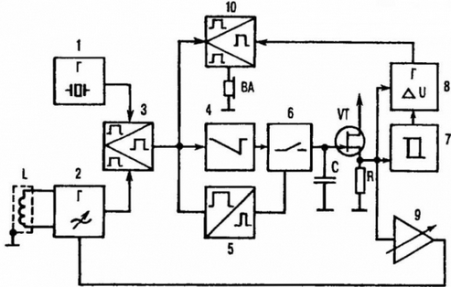
Fig. 1. The block diagram of the detector

Fig. 2. Plots of voltages and currents at the test points of the device
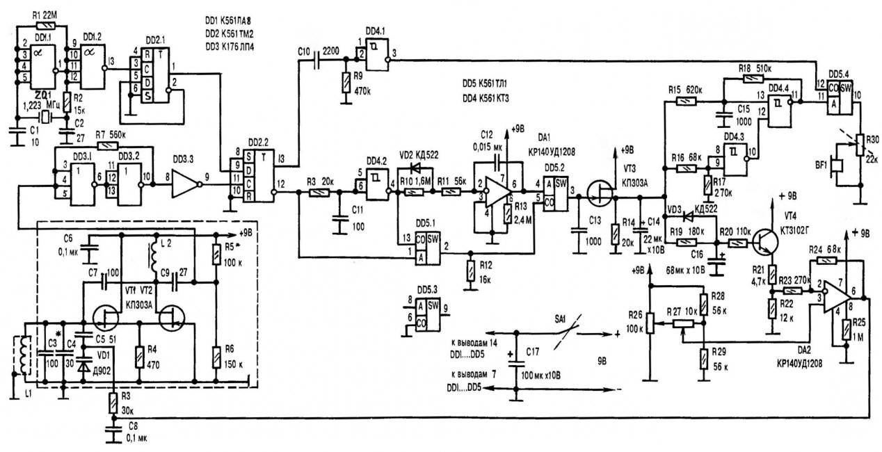
Fig. 3. A circuit diagram of the detector (click for enlarge)
Such an important parameter as a short-term instability, this generator small. Frequency drift during the first 10 s immediately after power is more than 0.7 Hz (every 30 min up to 20 Hz), while for normal operation the device is considered acceptable even 1 Hz for 1 min (without AFC).
Issued by measuring the generator of sinusoidal signals, with amplitude of 1-1. 2 In, is supplied through coupling capacitor C9 to the trigger DD3.2, which generates rectangular pulses with digital levels and duty cycle 2. R5R6 - divider, necessary for normal work of this section of the scheme. Well a DD3.3 performs the role of a buffer stage. The signal is fed to the mixer (T-trigger DD2.2). There also comes a frequency divider of the reference generator.
Features of work DD2.2 are such that if the inputs C and D of this logical item come two pulse sequences that are close in frequency, then the outputs signal is generated difference frequency with a strictly symmetrical square wave. All taken from the output 12 of the mixer, has the shape presented on figure 2A.
Direct and delayed (Fig. 2B) proinvertirovanny (due to the circuit and R8C11 element DD4.2) the signals are summed at the key DD5.1, plays the role of logical And/OR with the formation of short positive pulses of the recording (Fig. 2B) for the analog storage device (DD5.2, C13, VT3). But that's not all. Remove from the output DD4.2 the signal reaches the integrator, made by the classical scheme using VD2, R10 - R11, DA1, C12. Resistor R11 limits the current overcharging of the capacitor C12, unloading the output element DD4.2.
Integrated signal (Fig. 2G) using the key DD5.2, which control impulses with DD5.1, is supplied to the storage capacitance C13, where it is formed and before a new cycle the record is retained with high accuracy a voltage equal to the peak value that comes from the integrator (Fig. 2D). Capacitor C14 smooths out the effect type "step" that can occur when there is a sudden change of the frequency of the beats (Fig. 2E).
With source follower signal is supplied to the comparator DD4.3, GUN (generator, voltage controlled) and in the circuit loop of the AFC. The divider R21R22 together with R23 and R24 feedback constrict the range of the control voltage to an amplitude of 1.2 V. Operational amplifier DA2 compares with what is given by the divisor R26R29, and generates a voltage control aricopa VD1.
Resistor R26 is possible to set the starting point of capture AHR (sensitivity) roughly, a R27 - exactly. Moreover, when you move the cursor R26 towards the extreme (upper or lower scheme) regulations easily get out the capture area of IHD (±300 Hz), realizing the mode beat frequency "one to one", what makes the device more flexible.
For understanding of the functioning of the node, slowing the response to AHR on an abrupt change in the beat frequency, assume that at the base of the transistor VT4 there is, for example, some established Uб. Suppose also that at some the moment there is a sharp change of the beat frequency and, accordingly, the voltage on C14. A working scheme of our IU-teledetection necessarily respond to such "introductory" adequate deviation Uб transistor VT4 from previous values (thanks to the large values of R19, R20 and C16). And here is the response to a smooth change the frequency of the beats is sure to be a reaction to slow changes named stress.
When in the sensing range of the search frame sensor gets metal the subject and there is a relatively long time, on the base of VT4 is installed the voltage, which is usually enough to return at a specified frequency mode. But with a sharp tap of the sensor towards the situation changes, U6 transistor VT4 is not can quickly return to the previous level. That is, the conditions for crossing the "0" (the emergence of positive feedback). To last delete entered shunting R19, diode VD3, through which there is a rapid the discharge capacity C16 (return U6 on the set level).
In fact, the AFC has (depending on which side happens the beat frequency change) two time constants. As well as a special performance of sensor virtually eliminates the influence of the ferromagnetic properties of discovered items to increase fпоискового generator , and AHR, and the device in General work in all modes is quite correct. GONG (DD4.4, and R18, C15) converts the voltage varies with the beat frequency, in the frequency. And is configured by using divider R16R17 comparator DD4.3 allows him to do in the zone of maximum sensitivity when fбиений= 0-70 Hz.
The frequency of the VCO is input to A mixer (key DD5.4). The input TO come from logic element DD4.1 and differential fбиений, and formed differentiating circuit C10R9 (for best sound headphones, conserve power) short negative pulse. As a result at the mixer output is present or modulated fбиений the frequency of the VCO, or only the beat frequency. Furthermore, the transition from one mode to another scheme performs automatically. Variable resistor R30 is load & volume control, and combined with SA1 - power switch.
The use of chips of a series of CMOS operational amplifiers operating in microcurrent mode, helped to reduce the current consumption to the level of 6 mA, making acceptable use Krona battery as the power source.
Like other counterparts, almost all of the metal detector is mounted on a printed circuit Board from sided foil fiberglass. Search the generator is placed in shielding box made of tin. The dimensions of the Board only made the adjustment resistance R26, R27, R30, socket connect the power source and headaches phones, as well as frame sensor.
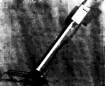
Technology and precision frame sensor is so important to the efficiency of the detector, which require, apparently, a more detailed presentation. As a basis here we have used a tourniquet made up of eleven 1100 mm pigtails PAW-1.2. Tightly wrapping a layer of electrical tape, wedge in an aluminum tube having an inside diameter of 10 mm and a length of 960 mm. The resulting workpiece is formed into the shape of a rectangular frame 300x200 mm rounded corners.
The end of the first wire, placed in an aluminum casing, electrostatic the screen sequentially soldered to the beginning of the second and so on until education kind 11-turn inductors. Adhesions are isolated from each other paper tape and filled with epoxy resin, while avoiding the appearance of closed loop through the bent frame tube.
It is desirable here to provide for any indoor high-frequency connector and suitable (non-metallic) mount for rod-arm, which you can use one or two sections from a collapsible fishing rods. The cable that connects frame with the block, better to use coaxial, television, for example, RK75.
The throttle 1_2 search generator (denoted hereinafter according to Fig. 1 and in accordance with the schematic circuit diagram of the detector, published in the previous issue of the journal) has 450 turns of wire PEL 1-0,01. Winding - the bulk on the frame with a diameter of 4 and a length of 15 mm with ferromagnetic core MNN (you can apply a suitable contour of the coil from the old radio). The inductance of this inductor 1 is 1.2 mH.
The device uses capacitors CSR or CTC (CL, C4, C5), KLS or km (C1, C2, C6 - C13, C15), K50-6 or K53-1 (C14, C16, C17). There is a choice and resistors. In particular, for the "trimmers" R26, R27 suitable SP5-2 or SP-3. The same thing we can say about R30 AC, only it needs to be combined with the switch.
All other resistors - MLT-0,125 (sun-0,125).
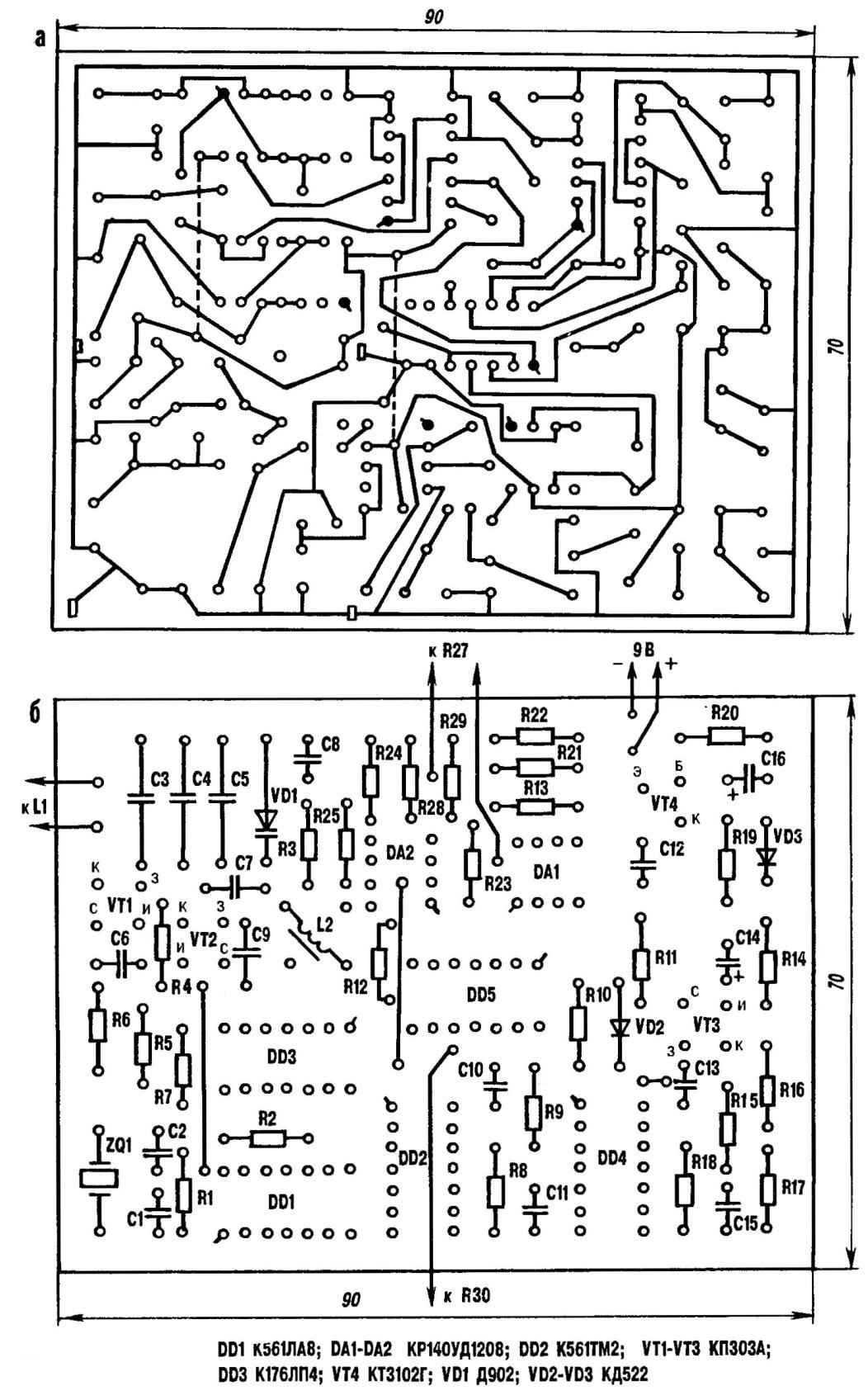
A printed circuit Board (click to enlarge)
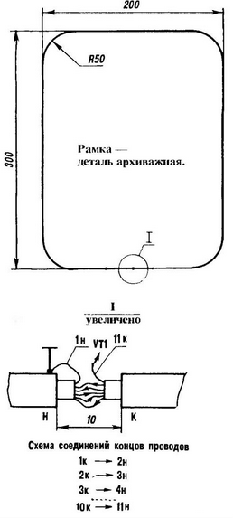
Installation dimensions
The device, seeing through the earth
Digital MS can be replaced by analogues of the well-proven series C. DD1, DDЗ-all from the same series, if only to contain the required number inverters.
Allow replacement and transistors. As VT1 and VТ2, for example, suitable KSSB (-F). On site \/TK is acceptable KPSS or CP (alphabetic index at the end the name in this case is not important), and CTG (VТ4)will replace CTA.
Quartz - one of those that is designed for 1.0 to 1.4 MHz. Choice of headphones also not limited. As practice shows, it is quite suitable TONE-1 ilicon-2. The varicap D can be replaced by D. Diodes VD2 and VD3 - KD522 (CD) with any letter index.
To configure the assembled device will need an oscilloscope and accuracy in… work. Carefully inspecting the entire installation, the scheme serves the power supply. Then check the current consumption, which is correctly executed operable structures should be 5.5 to 6.5 mA. When you exit the specified values look for and eliminate errors in soldering and G. D.
In the exemplary operation of the generator is convinced by the conclusion 1 chip DD2 frequency equal to 0.5 fкварцевого resonator with a duty cycle of 2. Then go to the "search engine" In the control point on the PCB where R3 and C8, served half of the supply voltage by disconnecting the circuit output DА2. And an oscilloscope connected to the drain of the transistor VT2, check the amplitude output voltage. She must be from 1 V to 1.2 V. If the deviation exceeds of 0.1 V. adjust the number of turns in the inductor L2.
But with the help of capacitors C3 and C4 exhibit the optimal frequency of the signal is equal to 0,5 fкварца . Moreover, the sensor itself must be located no closer than two metres from metallic objects. If necessary, selecting R5, seek symmetrical output signal at pin 9 of the chip DD3 (mixer must signal the difference frequency with a square wave equal to 2). Then, setting by changing the voltage on the varicap beat frequency, equal to 8 to 9 Hz, measure the signal at the output of the integrator 6 DA1 - it needs to be "on the verge restrictions on bottom". The corresponding correction is carried out the selection the value of resistor R10.
Attaching an oscilloscope to the source of the transistor VT3, check level change voltage depending on the beat frequency. Resistors R16 and R17 achieve to logical zero at the output of the comparator (pin 10 of IC DD4) appeared only when fбиений will be above 70 Hz.
VCO adjust resistor R15 so that the generator started to work, when the signal integrator "out of the restrictions from the bottom". In the future it significantly simplify the adjustment of the device before work, as the minimum the frequency of the MODES and correspond to the adjustment of the detector for maximum sensitivity.
Restoring on a printed circuit Board specially sealed connection of R3 and C8 with DA2, moving to the final stage of debugging of the device. Engine "podstroechnik" R26 turn in the extreme("positive") position that would fit the maximum beat frequency(and fпоискового generator> f model). Then, slowly rotating the engine in the opposite direction, begin to monitor the signal at pin 6 DA1. Notice how (at a certain position of the engine R26) on the screen oscilloscope emerges the moment of impact of the signal in the capture zone the AFC.
Continuing rotation of the handle trimmer 1327, get beat frequency, equal to 10 Hz, while checking the work of IHD (by desire of the signal to return in the initial state).
Engines resistor 1326, 1327, you must move slowly, mindful of the great the inertia of the AFC. In the head phones to listen the minimum VCO frequency and the faint clicks with f,beating. Some 1
cases may occur, "the voyage of the sound relative to some fixed state. In this case, should be chosen more precisely the ratio of the resistors R23, R24 or decrease the values of 1319, R20.
As already noted, the electronic part of the detector (which is almost the whole device) can be mounted in any suitable housing mounted on the handle. Care must be taken to the search frame sensor and connecting the wires were rigidly fixed relative to each other. After all, even minor the vibrations of these parts arising from the movement of the operator that can generate the wrong signal (especially at the maximum sensitivity of the scheme and inadequate experience with appliance). For the same reason, the blade should be worn behind bayonet upwards (away from the frame sensor). And the metal tips on the laces the Shoe operator is not allowed at all. Bring their interference threaten to undermine the no effort such an acute unit to unearth what it is so reluctantly parted.
Working with metalldetektoren little different from the actions of modern manual the mine detector. Of course, such a precise devices need adjustment. In our particular case is the rotation of the engine tuning resistor R26 to the extreme ("positive") position, and R27 in average. Filing for instrument power supply, rotate the adjustment knob R26 in the opposite direction until in head the phones have been ringing the GONG. After this trimming resistor R27 set the required sensitivity. And with R26 arbitrarily apply when working with the device in the mode beating "one to one") fбиений in the range of 200 -300 Hz.
AHR and VCO, in fact, disabled, therefore, the search is performed as usual. For a clearer determine the location of small items frame sensor bring to the area search or horizontally (rounded corner forward), or under the angle of 45 90° to the sample surface (with a clear positional advantage one of the sidewalls of the frame).
Author: Y. Stafiychuk