With this device you can measure the temperature in the vegetable and granaries in the room and on the street, and when placing sensors in the hive - to obtain additional information about the state of the bee family in the wintering period, what, in fact, was designed thermometer.
Measurement range of the thermometer is +50 and -50°C. the measurement Accuracy of 0.3°C (depends from the class applied microammeter). As the sensor diode is used D that shielded wire is connected (via a tape connector, mounted on the rear wall of the hive) with an electronic thermometer.
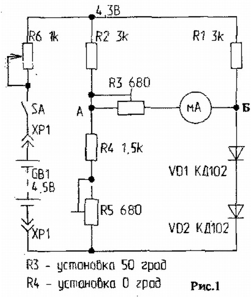
Let's consider a simplified diagram of the device (Fig.1).

Temperature sensor (i.e. heat-sensitive element) is a silicon diode. At room temperature through the open diode passes current 1... 2 mA, the voltage drop is usually 600 mV. With increasing temperature the voltage across the diode is linearly decreases by 2.2 mV for each degree Celsius. This dependence clearly is maintained in the range from 0 to 100°C. as a temperature indicator used sensitive microammeter with a zero in the middle of the scale, connected to the diodes sensors via a bridge circuit.
The bridge is considered balanced if the voltage at points A and B equally. When the heating of the diodes D1 and D2, which are the temperature sensors, voltage drop on them decreases. The bridge balance is disturbed and the digital value offset shows the meter pointer RA1.
Establishment and calibration
First disable the device PA1, turn the power on and check regarding the "-" voltage at points a and B. They must be equal to each other and to be in 1... 1.2 V. If the voltage at point B equal to the supply voltage (4.5 V), so the diodes incorrectly included, have their polarity reversed.
If the difference between the voltages at points A and B is small, it level trimpot resistor R4. Having achieved satisfactory result, set the minimum resistance of the resistor R3 included in the scheme pointer instrument and serves food. Then resistor R4 set the arrow mark on the device 20°C (room temperature) by controlling the temperature of mercury thermometer. Next, pinch your fingers measuring diodes and look at the arrow. It should gradually veer to the right and stop approximately at the division of 30°C. If the arrow moves to the left, it is necessary to change the polarity of the power the device on return.
Calibrated thermometer at two points - at the beginning and end of the scale. For calibration the starting point is used a vessel with melting ice taken from the freezer refrigerator. The temperature of melting ice is 0°C. Adjustment lead resistor R5. Then the temperature sensor (diode) immersed in water whose temperature is 50°C. In this case, the adjustment produced by the resistor R3. For reliability calibration of both ends of the scale do 3 times, by controlling the temperature of 0°C and 50°C mercury thermometer.
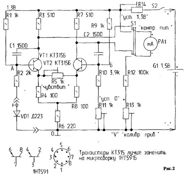
The scheme is more accurate and convenient thermometer is shown in Fig.2.

It is powered by a single galvanic cell at 1.5 V, which is important, and designed to measure the temperature at different points of the hive, which provides getting information about the state of the bee family.
As sensors are used, the diode D-223 or - if necessary - the group diodes. They can be combined on a flat tire or glass fibre laminate grouped on the wire, which is the common wire, and a separate pairs of wires for information at points spaced needed the distance. It should be noted that the resistance of the shoulder region (R2 resistor +the resistance of the diode or diodes D-223) must be equal to the resistance of the shoulder ABOUT (R10 + resistance of podstroechnik R11).
If the sensor is used one diode, the resistance of the resistor R10 approximately 3.9 kω, if three diodes D - about 5,9 ohms. It due to the fact that the resistance of the diode D is 720 725...Ohms at a current of through the diode is equal to I PR-0,4 mA and 16 Ohms at a current of 50 mA.
The thermometer is a balanced bridge, the diagonal of which is included the vapour phase amplifier with balanced output on the indicator. In the shoulder JSC bridge included resistance silicon transition, which is the temperature sensor.
The bridge composed of resistors R1, R2, R9, R10, podstroechnik resistance R11 and silicon junction diode D1. Vapour phase amplifier is built on transistors VT1 and VT2 type CTS, CT. It is desirable that the transistors were matched at a rate of gain. The collector load circuits are resistance R3 and R7. Resistor R6 is the common emitter resistor connection, a R4, R8 and R5. adjust the sensitivity of the cascades.
Shunt podstroechnik R5 determines the sensitivity of the device. Base transistors are blocked by the capacitors C1 and C2 included in the diagonal of the bridge. Microammeter to measure the limits 50-0-50 µa connected between the collectors triode. Power is supplied from item 1.5 V through a variable dampening resistor R14.
Setting
1. Set meals to 1.3 In using R14.
2. To close the database (deflection from "0" is allowed at +1 digit). If the needle deviates by more than one division, you should choose the resistors R3 and R7.
3. Open base VT1 and VT2. Lower the sensor into the water with snow or ice and set to "0" podstroechnik R11 - water Temperature controlled by mercury thermometer.
4. Lower the sensor into the water with temperature of 50°C. If the reading of the microammeter is not correspond to the point 50, the arrow should be set at this mark using a resistor R5.
5. Lower the sensor into the medium with zero temperature and check is set the needle on zero. If not, adjust R11.
6. Recheck readings RA1, lowering the sensor in water with a temperature of 50°C.
To control the power of 1.3 In, you should connect the ammeter to the circuit control, pressing SI - click P2K, then trimming resistor R14 to set the desired voltage. The voltmeter is calibrated using R13 in the range 0...5 V disconnect the thermometer from the power supply and the comparison of his testimony with an exemplary the voltmeter at this scale (0.. .5) resistance R12=100k, because R=U/I=5/0,05=100 K.
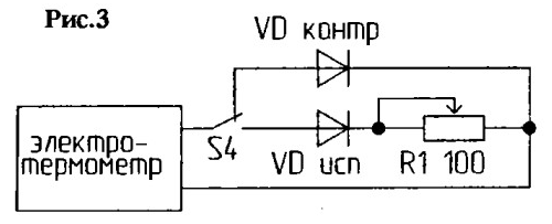
The diodes have a large spread of resistance, so they need to pick up. First, select one whose resistance is greatest when room temperature. Choose it using a digital voltmeter, multimeter type B7-20 or similar, as a tester to find the diode with the largest resistance is difficult, and the voltmeter can measure the voltage drop across the diode at a given current. This sensor will control. About him choose the additional resistance (attachments) to other diodes (Fig.3).

To the pins of the diodes being served to the wires to the diodes can be lowered into the water, the temperature of which is constantly monitored by a mercury thermometer. Using switch S4 exemplary control diode (which was adjusted the electrothermometer) and the subject alternately connected to the electrothermometer. Trimmer R1 achieve the same readings microammeter RA1. Then, by measuring a tester or a multimeter the resistance of R1 by podstroechnik disabled diodes, determine the resistance value of appendage - permanent resistance, which podpisyvaetsya in series with the diode test. So the same way attachments are selected for different diodes sensors. Matched diodes (with add-ons) are installed at the desired points in the hive, and are connected via connector to the thermometer. The screen wire connects to the negative rail, Central core - to R2 thermometer.
The thermometer can be applied in other branches of agriculture.
Author: A. Kukharenko, Grodno, Belarus


