The main purpose chip CRM [1] - smooth engagement and change the brightness of incandescent lamps control of other AC loads power up to 150 W, and the additional external thyristors and more.
The adjustment is usually carried out manually by means of the variable resistor, connected between pins 3 and 6 of the circuit and is shunted by the capacitor, creating the right delay time. But change is supplied to the load power can and electronically feeding the control voltage between the specified above conclusions (plus - 6), as is done, for example, in [2].
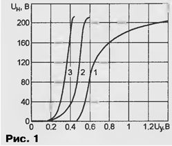
The main drawback of this method is unsatisfactory adjustment feature. In Fig.1 shows the experimentally filmed dependence the effective value of the load voltage UH on the control voltage Uy (curve 1). Except for a narrow Central portion, it is nonlinear, and when the control voltage is less than 0.47 In the load remains off.

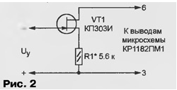
To improve the linearity of the electronic controller is possible by connecting, as shown in Fig. 2, between pins 3 and 6 of chip field-effect transistor VT1. With the increase the voltage between the source and the gate resistance of the transistor channel is growing that and leads to an increase of the load voltage of the chip CRM. The Resistor R1 limits the minimum resistance control circuit that reduces the "dead area to compensate for the variation of the primary current of the transistor.

The upper portion of the adjustment features largely linearized (curve 2 in Fig. 1). This is because the bending is compensated nonlinearity of the transient response of field-effect transistor in the mode close to cutoff. However, on the lower section of the adjusting the characteristics of the nonlinearity of the transistor plays a negative role as well it is seen from comparison of curves 1 and 2.
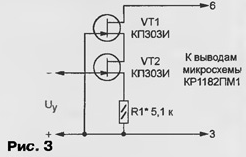
To further improve the linearity of the regulation can be achieved by collecting node control two transistors in the circuit shown in Fig. 3. The voltage at load in the range from 30 To up to a maximum of almost linearly depends on the Manager (curve 2 in Fig. 1).

The establishment of the regulator, assembled according to any of the schemes, is reduced to setting the initial current in the circuit of findings 3 and 6 of chip CRM. Replacing DC resistor R1 is adjusted, set the engine in position minimum resistance and zero when the control voltage is gradually increase the resistance until the output voltage starts to rise. After that the resistor is replaced by a constant, resistance, slightly less found.
The selection transistor QP AND as a control was not random. Compared to other field effect transistors its transient response has the greatest the deflection in the desired zone. You can apply the transistors QP and alphabetic indices B, C, W, by selecting the instances with a cutoff voltage of approximately 1 V.
Literature
Author: A. Pakhomov, Zernograd, Rostov region


