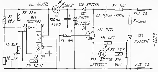
For the preservation of vegetables in the autumn-winter period of the year we use the container (a box with a double bottom), heated inside the bulb. Given temperature at the thermal stabilizer supports, made on the here the scheme. Used operational amplifier CUD (DA1) operating as a comparator, provides a constant set temperature of the air in "vegetable store" with an accuracy of 1°C.

The principle of operation of the device based on the unbalance of the measuring bridge, consisting of resistors R1 - R3 and the temperature sensor - the thermistor R4. The bridge powered by DC voltage stabilized by the Zener diode VD1.
The variable resistor R2 sets the threshold electronic parts, corresponding to the temperature of storage of vegetables - from 0 to +10 °C (assuming that the outside air temperature is lower than inside the container). In this case the voltage at the inverted input of the circuit DA1 is less than its direct log. This differential voltage operational amplifier converts in managing current, which opens the transistor VT1. Opening, the transistor includes SCR VS1, and he, in turn, - the heater Rнагрев in the anode circuit. At the same time the led turns on HL2, indicating the heater is turned.
Two or three incandescent lamps with a total power of about 200 watts to provide heat air in the vegetable store to the temperature set by resistor R2. Its increase leads to the decrease of the resistance of the thermistor R4, balancing the measuring bridge and, as a consequence, disconnect the heater from the mains. When cooling air to a predetermined temperature the resistance of the thermistor increases to the nominal value and the described process is periodically repeats.
A distinctive feature of the proposed heat stabilizer is powered electronic parts odnopoloi-readnum voltage network. Thus, when a positive half-wave AC voltage at the top (the scheme) conductor current network flows through the following circuit: fuse FU1 - limiting resistor R7 - the capacitor C3, the diode VD2 and charges the filter capacitor C1 to voltage 27 In corresponding to the voltage stabilizing Zener diode VD1, and further through HL1 led (power led) on the power of the chip of DA1 and measuring bridge to the fuse FU2. When a negative half-wave of the AC voltage on the same network wire current passes through the fuse FU2, diode VD3, the capacitor C3, the resistor R7 and the fuse FU1. It is easy to see that in this time, the transistor VT1, included the emitter follower, closed, missing, consequently, the control current of SCR VS1 (the requirement for THAT). When using half-wave rectified power, and impulse control SCR incandescent lamps burn dimly, that greater economy and the reliability of the device during operation.
Briefly about the parts of a thermal stabilizer. Temperature sensor (R4) is the thermistor MMT - 4 nominal impedance of 22 ohms. Transistor P701 (VT1) you can replace any of the series CT, KT807, KT815, CT, CT, CT, CT. Operational amplifier CUD (DA1) will replace any similar, including from other series. Variable (or adjustable) resistor R2 can be any type. The parameters of other elements of the device indicated on the diagram.
Author: V. Velichkov, Perm


