


")

The led indicator of this device the time periodically replaced by the value of the environment temperature in the place the location of the sensor is a conventional semiconductor diode. The device does not contain chips that require programming.
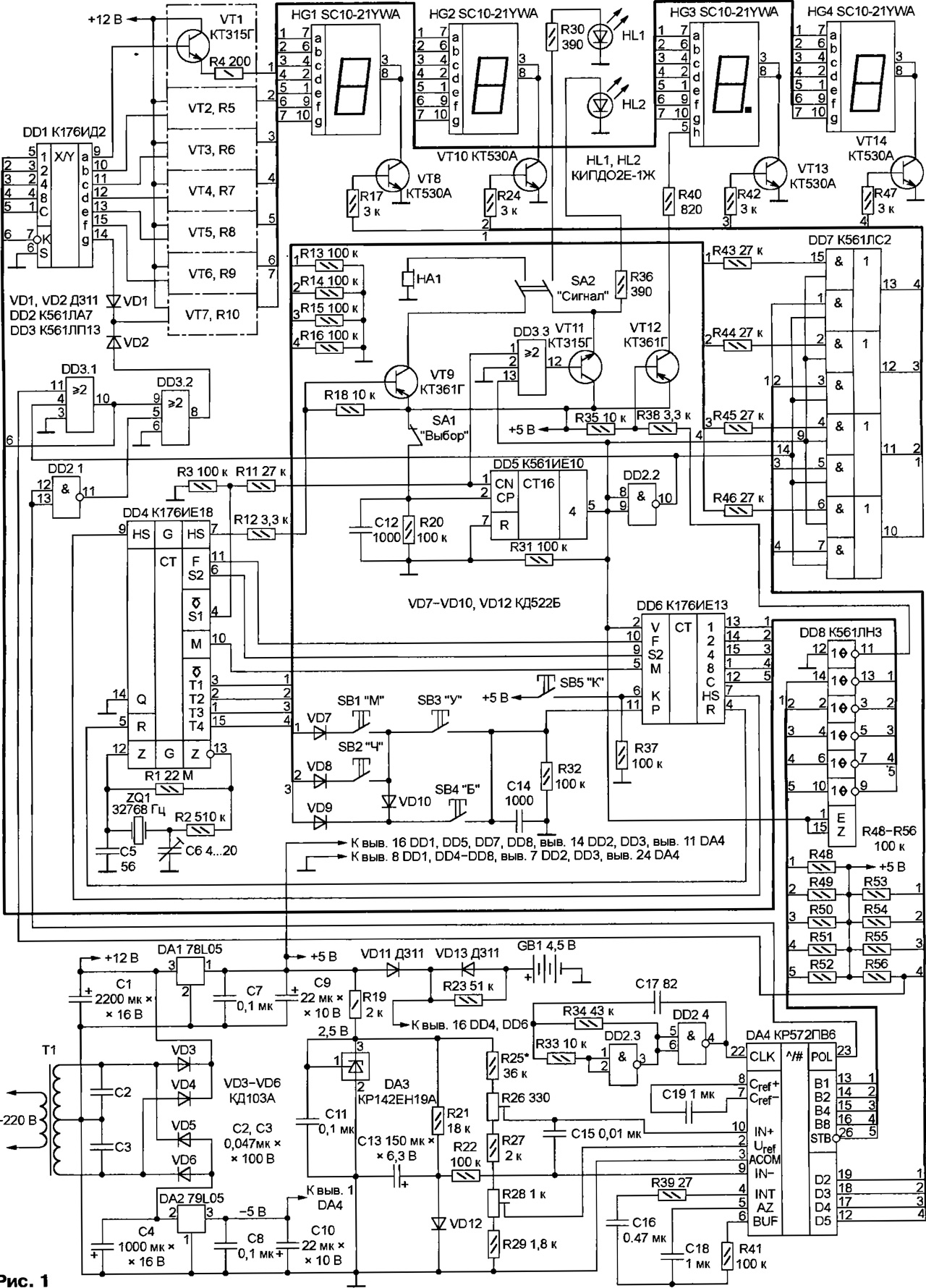
A schematic diagram of a clock-thermometer shown in Fig. 1. "Hour" part built on widely known chips CIE (DD4) and CIE (DD6). About the principle of operation and characteristics of the application can be read, for example, in [1].
(click to enlarge)
The basis of the thermometer serves as the chip CREW (DA4) - ADC dual integration is largely similar to the well known CREW and CREW. The main differences consist in the increased precision voltage conversion in code (4.5 decimal places) and output circuits, designed for connecting dynamic digital display.
BCD codes for the digits of the result of the conversion alternately appear on the outputs B1, B2, B4, B8. Each figure is accompanied by a high logic level on corresponding output D1 (senior decimal place, in this device not used) - D5 (LSB). Output pulse STB mark the shift digits Logic level at the output of the POL says about the polarity of the result: 1 - positive, 0 negative. Necessary for the chip clock DA4 a pulse frequency of approximately 120 kHz received at its input from CLK generator on the elements DD2.3 and DD2.4.
On the chip CREE (DA3) assembled a voltage regulator 2.5 V for the measuring circuits of the thermometer. The capacitor C11 prevents spurious generation. Resistor R21 is set current (approx 0,14 mA) via the temperature sensor is a diode VD12. The voltage across the diode at a constant current linearly temperature-dependent, is input IN chips DA4. At its entrance IN+ with engine tuning resistor R26 voltage equal to the voltage on the diode VD12 at a temperature of 0 DC, approximately 600 mV.
Exemplary voltage of 200 mV at the input Uref ADC trimmer set resistor R28. It is this value (in absolute value) would have reached the potential difference of the inputs IN+ and IN - at the temperature sensor ±100 °C. Almost interval measured temperature is -60…+99,9 °C.
Chain R22C15 protect the ADC input from pulses. Capacitor C19 is storage reference voltage. Capacitor C16 and resistor R39 - elements integrator. Capacitor C18 is included in the circuit of the automatic zero correction ADC. Diode VD12 schuntermann capacitor C13 to eliminate the interference frequency of 50 Hz, which can significantly distort readings. On the work of such a thermometer can be found in [2].
Chip CLS (DD7) - the four elements AND-OR General Gating inputs - in turn connects to node two indicators signals source selection discharge indicator: outputs T1-T4 chip DD4 in display mode or time outs D2 - D5 chips DA4 in the temperature indication mode. The signals from the outputs elements DD7 control transistors VT8, VT10, VT13, VT14, alternately including indicators HG1-HG4.
The inputs DDI - Converter binary-decimal code in semielemental - the signals from the outputs B1, B2, B4, B8, STB chip DA4 come through repeaters chip DD8. To his (Converter DD1) inputs and outputs connected chip DD6 However, the control signal applied to the input V DD6 and the inputs of E and Z DD8, allows you to be active only outputs one of these chips, translating the other outputs to inactive (Vysocina-DANCEE) state Passive state outputs of the chip DD6 does not affect the process of counting time.
As a result in the log. 1 at pin 5 of the counter DD5 indicators HG1-HG4 display temperature, and in the log. 0 - time. The input of this counter CN come second the pulses output from the
51 chip DD4, so every 4 output level 5, and with it the mode display change. Upon opening the contacts of switch SA1 counter will stop in the same condition in which it was at the moment of tripping. The contacts switch SA1 will resume the periodic change modes.
Through the current amplifier transistors VT1 to VT7 output signals of the transducer code DD1 fed to the anodes of indicators HG1-HG4. In display mode temperature "extra" senior discharge indicator extinguished input To the Converter DD1 signal generated by the element DD3.1. The output signal of the element DD3.2 when negative temperature includes the indicator HG1 element g - minus sign.
Element DD3.3 and the transistor VT11 control the LEDs HL1 and HL2. Mode temperature indication both LEDs are extinguished. In display mode time led HL2 is blinking with a frequency of 1 Hz, a HL1 - only when closed the switch SA1. The second group of contacts of the switch, completing the circuit emitter HA1, solve the beeping alarm.
As the entrance 12 of the chip DD8 is connected to the common wire, in the active state (temperature indication) high logic level from the output 11 of this chip through the switch transistor VT12 includes the indicator HG3 element h - decimal point between the digits of ones and tenths of a degree.
Resistors R48-R56 necessary to increase the voltage high logic level at the chip outputs DA4. Resistors R3, R13-R16 - load in chains the outputs of IC DD4, open source.
The node power supply consists of transformer T1, and two full-wave rectifiers. One of them (diodes VD3 and VD4) gives a voltage of +12 V for power the anode circuits of the indicators HG1-HG4. From it by an integral stabilizer DA1 receives a voltage of +5 V to power the circuits of the device. From voltage of the second rectifier (diodes VD5, VD6) using integral stabilizer DA2 get a voltage of -5 V, the required chip ADC DA4.
As the transformer T1 can be used any network with two secondary windings 9 of 12 V with a load current of 300 mA. Circuits DA1 and DA2 will replace any integrated stabilizers, respectively, positive (for example, CREA) and negative (e.g., CRE) voltage 5 V. The negative voltage stabilizer in an extreme case may be parametric on the Zener XA. Consumed by the circuit -5 V current exceed 3 mA.
Battery backup power GB1 - three galvanic cell, size AA, connected in series. It is designed to keep the watch running in the absence of mains voltage. In this case, the voltage from the battery flows through the diode VD13 only on "time" chip DD4 and DD6. To the rest of the chip, left without power, affecting mentioned in linking their chains of series-connected resistors R11, R43-R46, and a resistor R31 in the mode of backup power maintains a low logic level at the input V IC DD6. Resistor R23 provides recharging GB1 when working from network.
Copy clock-thermometer is assembled in a plastic housing of hours radiokonstruktor electronics. Parts installed on several boards of fiberglass and are connected in a hinged largely insulated wires. Access to axes of trimming resistors R26 and R28 - through holes in the back corps.
Is indicated in the diagram of the led indicators SC10-21YWA you can use any others with common cathode, the appropriate size and color of the glow. LEDs HL1, HL2 is placed in the gap between the indicators HG2 and HG3. As transistors VT8, VT10, VT13, VT14, you can use any silicon structures n-p-n current transfer ratio of not less than 180 and maximum collector current at least 300 mA. When selecting a replacement pay attention to residual voltage collector - emitter in saturation mode that significantly affects the brightness the illumination of the indicators. In transistors CTA it does not exceed 0,13 V.
A sound emitter HA1 - compact electromagnetic imported from alarm. Instead, you can successfully use a dynamic driver with voice coil resistance not less than 30 Ohms.
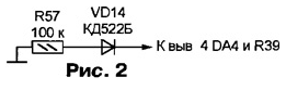
Imported chip CREW - ICL7135 or TLC7135. Some instances of such ADCS suffer from "the warp" features - results convert positive and equal in absolute value negative voltages are slightly different (not counting the level at the output POL). Eliminate bias through the diode-resistor circuit, connected as shown in Fig. 2.
About the establishment of a one-hour portion of the device is explained in detail in [1]. As for calibration thermometer temperature sensor (diode VD12) is placed in melting ice or snow and a trimming resistor R26 achieve zero indication on led indicator. If this fails, choose the value of the resistor R25. Then, dropping the sensor in hot water with a temperature-controlled model thermometer, resistor R28 is established on the corresponding indicator value.
The brightness of the indicators HG1-HG4 and LEDs HL1, HL2, if necessary you can increase or decrease, choosing the values of resistors R4-R10, R30, R36.
In conclusion, I would like to share experience installing outside temperature sensor of the room. It needs to stay as far away from Windows and walls of the house, well to abbatissa wind, but to be concealed from direct sunlight. Best place - the external part of the balcony railing. Perpendicular to it is attached a horizontal wooden bar section of 30x30 mm and a length of approximately 500 mm. On a remote from the balcony the end of the bar at an angle of 30° sun visor set size 300x300 mm of plywood with a minimum thickness of 10 mm. Under the canopy on 40…60 mm from the center of its bottom surface and place the diode VD12, pre-placing it in a waterproof capsule of suitable size, for example, of medicine. The hole in the capsule, through which withdrawn the connecting wires should be sealed.
Literature
Author: V. Surov, Gorno-Altaisk