


")

Described herein thermometer allows you to measure the temperature at certain points motor, transformer, transistor package, diode, soldering iron tips, and other devices. The ranges of measured temperature 0…100°C 0…1000°C .
Temperature sensor thermometer thermocouple is "chromel-alumel", welded from wires with a diameter of 0.2 mm. the Value generated by the thermocouple EMF proportional, as is known, the temperature difference between "hot" and "cold" to her ends. In the electronic thermometer in question, provided automatic temperature compensation of thermocouple cold ends t. ("room"). to the measuring device showed a temperature of the object t. not the difference t - t.
Schematic diagram of the thermometer shown in the figure.
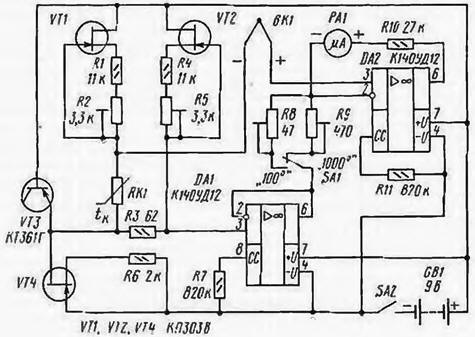
It consists of the measuring bridge (VT1, VT2, RK1, R1-R5). voltage stabilizer power (VT3, VT4, R6), thermocouple BK1. amplifier (DA1, DA2, R7 - R11, SA1), microammeter RA1, power switch SA2 and the power source GB1.
In the lower arms of a bridge circuit included copper thermistor and resistor RK1 R3, in the upper - stabilizers currents of these resistors on the transistors VT1 and VT2. and in the measuring diagonal thermocouple BK1 and reinvestiruja inputs chip DA1, DA2 amplifier. Due to the very high input resistance amplifier current in the measuring diagonal is virtually absent, and on his input voltage (Uw) is not influenced by the voltage drop across the resistor R3. RK1 and the conductors of the thermocouple. Cold junction of the thermocouple must be in the body thermometer.
When the temperature t (at constant t) the voltage across the thermistor RK1 (Urk1) and thermocouple EMF E change b out of phase so that their sum is always remains constant. To zero on the scale of the measuring device RA1 consistent with the temperature of 0°C and the thermometer did not depend on temperature tk, the voltage across the resistor R3 is set equal URз = UПк10 = K/LRx. (1). where Urk1o - voltage at t RK1.=0°C; K - coefficient Seebeck coefficient of the thermocouple: LRK1 - temperature coefficient of resistance of the resistor RK1. The dependence (1) fair in observance of inequality: LRk1 " LR3 (2). This condition is easy run, if RK1 wound copper wire, and R3 to use the resistor. In compliance with the requirements (1) and (2) input voltage Uk = K·t (3). This same voltage is applied to resistor R8 (in the range of measured temperature 0…SS) or to the resistor R9 (in the range 0… 1,000 TIMES). because Oh DA1 is connected to the circuit of a voltage follower, and OU DA2 - scheme einverseremove amplifier. Consequently, the current in the feedback circuit PA1. R10 will be equal to: loc=Uвх/R, where R is the resistance of the resistor R8 or R9. Taking into account equality (3) κ OS = K · t/R, i.e. the current through the microammeter RA1 right is proportional to the temperature of the object t.
As RA1 used microammeter of 100 μa. The resistor RK1 wound but the plate of the PCB 20 x 10 mm 1 mm thick insulated copper wire with a diameter of 0.1 mm to resistance 60… 100 Ohms. Transistor VT3 is included as the voltage of the measuring bridge. Its functions can be performed by any low-power silicon transistor with a breakdown voltage of the junction, the base-emitter below 7 V. the Transistors VT1, VT2, VT4 - any low-power field-effect transistors with p-n the transition cutoff Voltage VT1. VT2 - no more than 4 V. a VT4 - not more than 2 V. The sum of the cutoff voltage of the transistor VT4 and voltage stabilizing transistor VT3 must be less than the battery voltage GB1. and the smaller the amount, the when deeper battery discharge thermomet will keep working.
Micropower opamps applied only for reasons of minimum energy consumption. When powered thermometer from the network as DAI, DA2, it is desirable to apply precision op amp. Trimmer resistors R2, R5, R8, R9 - multi - SP5-2V or others like them. The remaining resistors - MLT-0.125.
Establishing thermometer nachiket to calculate voltage UR3. For thermocouple "chromel - alumel" To = 4.065·10-2 mV/°C. For copper LRK1 = 4.3·10-3/°C. Using equality (1). received URc=4.065·10-2/ 4.3' 10-3 = 9,453 mV. Further, closing the switch SA2. parallel to the resistor R3 is connected voltmeter (preferably digital) and resistor R5 sets the calculated stress with the maximum possible accuracy. After that, the switch SA1 is moved to "100°". lower end in a container of melting ice and resistor R2 install arrow micro-ammeter PA1 to 0. If resistor R2 or the P5 lacks limits regulation, it should be replaced, respectively, of the resistor R1 or R4. Then lower end in a vessel of boiling water and a resistor R8 set arrow PA1 to the last division of the scale is 100 μa. Next, without removing the thermocouple from boiling water, transfer switch SA1 to "1000° and resistor R9 set the arrow PA1 in position 10 μa. The building finish.
During device usage peaks in the arrow PA1 at the limit of measurement 100°C at room temperature says the battery is discharged GB1 and the need replacement. The maximum voltage of the thermometer is determined valid the supply voltage of the OS (for chips COD UMa.c=15 V) or a valid voltage drain-gate transistor VT4 plus the voltage stabilization transition the base-emitter of the transistor VT3. The minimum supply voltage is different to the sum of voltage stabilization and voltage VT3 of the cutoff transistor VT4 (the author Yiming was 7.5 In) the current consumed by the thermometer, and 0.6…0.9 mA.
When measuring negative temperatures, it is necessary to swap the ends connect the thermocouple to the thermometer.
Thermocouple "chromel-alumel" used by the author because of its high working temperature (up to 1300°C). If the limit of the measured temperatures do not exceed 500°C, you can take thermocouple "chromel-Copel" or weld the thermocouple from the other, available, pair of metals (alloys). It is obvious that the new couple will to have a different value of the Seebeck coefficient and To respectively other the value of Ug. The value of the coefficient K can be calculated by taking from the directory the magnitude of the thermopower of these metals in a pair of platinum and subtract them from each other, or To determine the value experimentally. The thermocouple should to connect to a digital millivoltmeter and place it end-first into the vessel with with melting ice, and then into a vessel of boiling water, recording the readings voltmeter (considering the sign). Then you need to find the difference between the obtained values and divide it by 100.
In conclusion, I would like to mention the advantages of the thermocouple in front of other sensors temperature. First, small size (ball diameter of the thermocouple, welded from wire of diameter 0.2 mm, less than 0.5 mm; if the wire is thinner, and the ball will be less). Secondly, interchangeability, i.e. the ability periodic connections to one thermometer any number of thermocouples, installed on different objects or at different points of the same object. With semiconductor thermistors or diodes is impossible due to scatter them parameters. Thirdly, high operating temperature, which makes the thermocouple indispensable in the measurement of temperatures above 15°C. fourthly, miserable the cost and ease of fabrication and repair. Fifth, the vast majority of cases, the lack of the necessity to isolate the thermocouple from the environment, even when measuring the temperature of the electrolyte. Due to the low value of the thermopower an electrochemical process in the thermocouple impossible, so it is not an electrolyte closes, of course, provided that the materials of the thermocouple are not chemically interact with this electrolyte.
Author: V. Burkov, Ivanovo