The difference between this version of the heat stabilizer from many other, previously described in our magazine is primarily in the replacement of traditional SCR a triac, which has eliminated the rectifier bridge composed of powerful diodes. As a result, the number of elements mounted on a heat sink with the output power up to 1 kW, was reduced from five to one. The heat stabilizer can be used to maintain the temperature in the house in the garden, in the cellar, balcony "growers" and other closed spaces.
The temperature stability of the proposed electronic device, is carried out, as usual, the switching on and off of the mains voltage supplied to the load is a heater, depending on the temperature sensor - the thermistor. The inclusion of the triac occurs near the moment of transition network voltage through zero, which reduces the noise level.
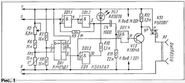
Diagram of a heat stabilizer is shown in Fig. 1. In the heat stabilizer used the power node and the circuit forming pulses at the moments of passing network voltage through zero, is described in [1], so that part of the circuit completely repeating Fig. 1 [1], not shown here.

"zero" is formed by a pulse of negative polarity. Schmitt trigger, assembled on the elements DD1.1, DD1.2 and the resistor R9, forms a steep fronts and downs of this impulse. Positive differential voltage corresponding to the beginning of halftime, differentiated chain C4R11 and in the form of a short pulse of positive polarity is fed to the input terminal 12 of the element DD1.4.
Simultaneously to the second input (pin 13) of the element DD1.4 receives the signal output from the Oh DA1, performing the function of the comparator. Its inputs connected to the outputs thermosensitive bridge formed by resistors R5 - R8 and a thermistor RK1. While the temperature of the thermistor above the resistor R5, the voltage at the noninverting input of op-amp is less than the inverting, the output the comparator is formed by a low-level signal. At this time the pulses using the element DD1.4 do not pass and HL1 led is closed.
When the temperature of the thermistor RK1 will decrease and the voltage across it will be more the output signal OS will correspond to the high level, the led will light HL1, the pulses from the differentiating network C4R11 will begin to pass through the element DD1.4 to the base of transistor VT3. At the beginning of each half cycle, the transistor will start to turn on the triac VS1 and thereby connect to the network load - heater.
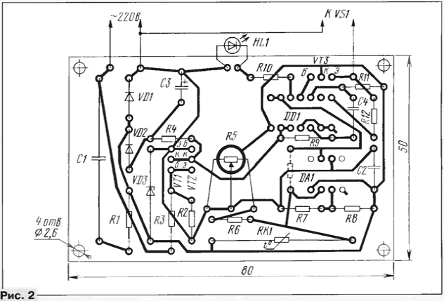
All elements except the triac and the nesting part of the output connector X1, mounted on the PCB size 80x50 mm (Fig. 2). The fee made of one-sided foil fiberglass, designed for the installation of resistors MLT, capacitors K73 - 16 (C1), K50 - 6 (C2), km - 5 (the rest). Variable resistor R5 - SDR - 4m or SDR - BM. Diodes VD1 and VD2 - any pulse or silicon rectifier, Zener diode VD3 is the voltage stabilization 10...12 V-Chip CLA interchangeable on CLA or CRL. Transistors VT1 and VT2 can be any low-power silicon structure p-n-p, transistor VT3 - medium and high power same structure with valid collector current up to 150mA.

Function comparator (DA1) can run almost any OS, operating at full supply voltage of 10 V and consumes a current less than 5 mA, for example, CRUD, CUD, CRUD, CRUD. Led HL1 - any of a series of AL307. It should be possible to endure well beyond the Board, and "watch" it needs in the same side, and the shaft of the variable resistor R5. The body of the resistor R5 is connected to negative conductor of the supply circuits that are necessary for its shielding.
The thermistor RK1, used in the manufactured sample of the device - MMT - 4. But the fit and any other series of MMR or KMT on nominal impedance 10...33 ohms. Better - sealed MMT - 4 or KMT - 4 [2, 3].
For determination of the resistance of resistors R5 and R6 should be set range temperatures, in which the heat stabilizer. Resistance the thermistor is measured at maximum operating temperature. The same resistance less or more must have and a resistor R6. Then measure the resistance of the thermistor at a minimum temperature and choose the resistance of the resistor R5 such that it is in the sum of the resistance of the resistor R6 was less than the measured. If there are difficulties in measuring the resistance the thermistor in the temperature range, we can assume that for series resistors MMT it increases by 19% when decreasing the temperature by 5°C, 41% belittling of 10°C and twice at 20°C. Similarly, when the same increase the temperature decrease of the resistance of the device is 16%, 29% and twice respectively. For thermistors KMT this change is about 1.5 times more.
Indicated in the diagram, the values of resistors R5, R6 and the thermistor correspond RK1 the range of heat stabilizer 15...25°C.
Circuit Board and triac COG (or COW) mounted on ribbed heat sink dimensions 60x50x25 mm, placed in a plastic box the size of 150x95x70 mm so that the thermistor was close to the bottom wall of the box and heat sink triac - to the top. Previously in these walls of the housing smallest drill possible ventilation holes with a diameter of 6 mm with a step of 10 mm. Led and shaft output through a resistor the openings in the front wall of the box. The shaft of the variable resistor and mounting screw the plastic handles on it should not be available for random touch.
To establish and calibrate the controller is started without a triac. The output 12 of the element DD1.4 temporarily connect a wire jumper from the output 14 of this chip, and the resistor R12 is connected a DC voltmeter. The Capacitor C1 shunt resistor 220...330 Ohms, then the thermal stabilizer connected to the constant current source with an output voltage of 15 V. 12... The voltage of this source set such that the current consumed a heat stabilizer, was within 18...20 mA.
The thermistor is placed in water, the temperature of which corresponds to the middle the operating range. The insulator of the thermistor should not touch the water. During the rotation the shaft of the resistor R5 clockwise HL1 led should light, and voltmeter to show the voltage of about 9 V, while rotating it in the opposite direction the led will extinguish, and the needle of the voltmeter to stand at zero scale mark. Make a corresponding mark on the scale of the variable resistor. Changing the temperature of the water, completely graduate the heat stabilizer.
For this you can instead use a thermistor constant resistors with values corresponding to the measured resistance thermistor at given temperatures.
Removing the additional resistor and jumper wire, fully assembled stabilizer and checks his work with bulb attached to the connector X1 "Load".
For linearization of the scale of the variable resistor, you can use the recommendations of the article [4].
The regulator is installed in a vertical position so that the ventilation the holes in his case does not close, for example, on the wall of the room. If the heat stabilizer is used to maintain the temperature in the cellar, incubator or balcony "vegetable store", it is better to put out thermostabilizing volume, and the thermistor to make the housing of the stabilizer. In this case reduce the influence of interference at the location of the thermistor on the Board should be oxide capacitor of at least 50 μf at a rated voltage of not less than 10 V. the thermistor and lead wires to it must be carefully isolated.
The thermal stabilizer has no hysteresis in temperature, and its accuracy can be very high - on the order of 0.1°C. But if for some reason the hysteresis still is required, you must include between pins 3 and 6 OU DA1 resistor (in Fig. 2 it is shown by a dotted line) impedance of several megohms.
Literature
Author: S. Biryukov, Moscow


