In this device (unlike most other described in Amateur literature) as a sensor of thermocouple used. It significantly expands the field of application of the proposed device. It is suitable not only for greenhouses and vegetable stores, but also for drying racks and even furnaces.
The stabilizer keeps the temperature within the specified range by turning on and off the electric heater. The maximum switched current to the load (heater) - 0,1 A at a voltage of 220 V, and with an additional triac-s ' key - Interval 80 A. controlled temperature 0...500 °C with a chromel-Kobeleva thermocouple or 0... 1200 °C with a chromel-alumel. Current temperature is displayed on led digital indicator. Measurement error is not more than 1.5% top the boundaries of the interval. The accuracy of the temperature stabilization is largely dependent on thermal characteristics of the object (chambers and nested objects) and mutual the location of the thermocouple and heater.
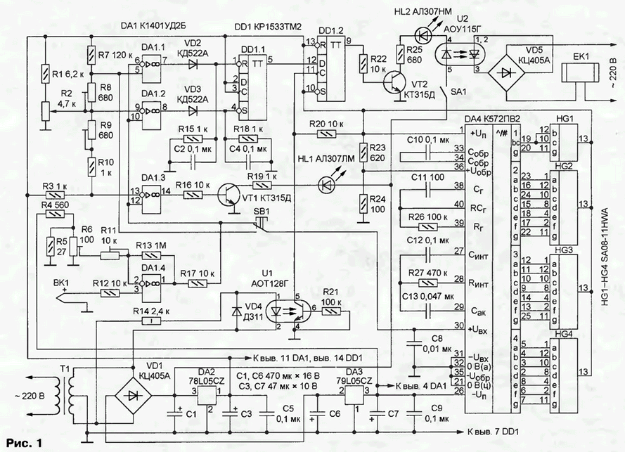
Schematic diagram of the device depicted in Fig. 1. The voltage developed thermocouple BK1 and reinforced shelter DA1.4, is fed to the inputs of the shelter DA1.1 - DA1.3, serve as Comparators. Thresholds of response is set by the voltage dividers on the resistors R1-R3, R7 - R10. Resistor R2 sets the temperature threshold, below which should be included heater EK1. The temperature difference between the on and turn off the heater is controlled by resistor R8. Resistor R9 set the threshold of the comparator at the shelter DA1.3. If you exceed this the threshold comparator is triggered, the VT1 transistor opens, as a result HL1 led is lit, indicating an unacceptable temperature rise in the controlled area.

(click to enlarge)
Chain VD2R14C2 and VD3R17C4 protect the inputs of the trigger DD1.1 from negative the voltage at the outputs OS and interference. Depending on the state of the comparator DA1.1 and DA1.2 at the output 5 of the flip-flop is set low or high logic level. The second trigger (DD1.2) serves for the synchronization points of entry and turn off the heater with a zero phase voltage, which greatly reduces generated by the device noise. The input of the trigger DD1.2 filed impulses formed by means of an optocoupler U1 voltage from the secondary winding of the transformer power T1.
The output 9 of the trigger DD1.2 is connected to the switch input on the transistor VT2. In the collector circuit of the transistor included led HL2 (signaling turn on the heater) and the led of optocoupler U2. The switch SA1 is used to forcibly turn off the heater.
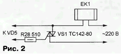
The thyristor optocoupler U2 is the diagonal of the diode bridge and VD5 commutes the load is an electric heater EK1. Naturally, consumed by the heater current is not must exceed for the thyristor bridge of values is More powerful the heater can be connected according to the scheme shown in Fig. 2.

Triac VS1 needs to be provided with a heat sink.
Node display the current temperature and the desired value is assembled on chip DA4 CPU (foreign equivalent - ILC7107), detailed description of which can be found in [1]. The chip included in the model scheme, with its outputs connected semielemental led indicators HG1-HG4. If necessary, you can apply liquid crystal display, replacing the chip CPW on CPW as described, for example, in [2].
If the button SB1 is pressed, the input 30 DA4 comes proportional to the current the temperature voltage with the output OU DA1.4. Otherwise DA4 measures a voltage proportional to the installed resistors R2 and R8 temperatures heater activation.
The feeding unit consists of a transformer T1 with a rectifier diode bridge VD1 and two integrated voltage regulators - DA2 (+5 V) and DA3 (-5). Voltage collector circuits of the transistors VT1, VT2 are not stabilisierung. Overall capacity of the transformer T1 - 5...10 W, the secondary winding is voltage 15...20 V with a branch of the middle.
The device can be used fixed resistors MLT, trimming - SP5-2, variable (R2) - SDR-45, capacitors K73-17 (C10, C12, C13), oxide - K50-35 or their foreign counterparts, other ceramic, for example, km-6. OPTRON AOG can be replaced by SOUTH Instead of LEDs SA08-11HWA Kingbright company fit others with common anode, for example, Paralight A-561SRD or CLCV - CLCE.
In the temperature range 0...1200°C as a thermocouple used ready BK1 a chromel-alumel sensitivity 40,65 µv/C. If the maximum temperature not more than 500 °C, suitable and chromel-Kobeleva (72,85 µv/°C). In this embodiment, the value of the resistor R2 is reduced to 2.2 kω.
In the absence of the finished thermocouple is produced by combining spot welding the ends of the wire segments from the respective alloys and connecting to opposite ends of a conventional copper wire to a length of several meters. To shield these wires is not necessary, however, you should not lay them near power circuits or wires on which significant flow of high-frequency and impulse currents. On some peculiarities of the construction and use of thermocouples you can read, for example, in [3].
Instrument setup is to install a trimming resistor R6 right the evidence led at minimum, a resistor R11 is when the maximum temperature. These adjustments are interdependent, so they should repeat a few times. To achieve the desired for chromel-Kobeleva thermocouple gain shelter DA1.1 have to decrease the value resistor R13. In conclusion, the resistor R8 sets the required difference temperatures on and off the heater and the resistor R9 is the turn - on threshold alarm accidental overheating.
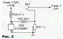
It is known that EMF generated by the thermocouple is proportional not absolute values, and the temperature difference between its hot and cold junctions. To to eliminate the resulting additional error, you need to take care of the constancy of temperature of "cold" (non-working) of the thermocouple or compensation its changes. One of the possible schemes of compensation node shown in Fig. 3.

The numbering of parts on it continues on the previous figures. Thermosensitive chip DA5 CEM [4] located in close proximity to the cold junction and in thermal contact with it. Part output voltage DD1 chip stack generated by the thermocouple BK1. With appropriate ratio of the resistances of resistors R30 and R31 voltage the input of op-amp DA1.4 will depend on the temperature of the "hot" junction.
Literature
Author: V. Twsnow


