


")

The descriptions of the different electronic digital thermometers repeatedly have been published the journal Radio. Usually they contain Converter temperature-frequency and measuring the honour not discrete digital elements that convert the measured frequency to the temperature. Built not discrete Converter temperature-frequency requires calibration and allows you to achieve an acceptable accuracy in a rather limited the interval (due to the nonlinearity of the temperature characteristics of elements). Application modern components - microcontrollers and special sensors - greatly simplifies the circuitry of the device while increasing functionality and precision of measurements.
A schematic diagram of the thermometer shown in Fig. 1.
It is based on popular microcontroller (MCU) PIC16F84A (DD1). To measure the temperature used integrated digital sensor (BK1) firm MAXIM DS18B20. This the chip requires no calibration and allows you to measure the temperature of the environment from -55 to +125 °C, and in the range -10.. .+85 °C manufacturer guarantees an absolute error of ±0.5 °C. the Sensor DS18B20 - the most perfect of the widely known family DS18X2X, previously under the trademark of Dallas Semiconductor. Unlike functional analogues and DS1820 DS18S20 it before starting the measurement allows you to set the desired relative the accuracy of the transformation temperature from the following series of values: 0,5; 0,25; 0.125 and of 0.0625 °C, while the measurement time respectively equal to 93.75; 187,5; 375 and 750 msec.
The principle of operation of the sensor DS18X2X based on counting the number of pulses, generated by the generator with low temperature coefficient in a temporary the interval formed by generator with a different temperature coefficient, the internal logic of the sensor is taken into account and compensated for parabolic the dependence of the frequencies of both oscillators to temperature.
The exchange of control commands and data between the sensor BK1 and MC DD1 working at a frequency of 4 MHz, is carried out on a single-wire bi-directional bus transfer data 1 - Wire. Each instance of the DS18B20 has a unique 48-bit number recorded with a laser in the ROM in the production process, which allows to connect to one bus virtually any number of such devices. Limiting factor is basically only the total time spent on sequential polling of all sensors connected to the network.
With period equal to 1, MK DD1 sensor sends BK1 team at the start of the process measure the temperature with an accuracy of 0.0625 °C and receives from him the result the previous calculation. Accepted udatsya 12-bit code corresponding to the measured temperature, converted to decimal form, rounded to the tenths degrees and displayed on the led HG1 in dynamic mode. Feed voltage log. 0 on one of the outputs RAO, RA1 or RA2 MK includes the corresponding order of the indicator, displaying on the outputs RBO-RB6 semielemental code displayed in the discharge figures. Management is on point the indicator that separates the integer part of the temperature display of the decimal, MK produces through the open-drain output RA4. Display all three indicator bits is approximately 12,3 MS (frequency of 81 Hz).
Since the device is applied to a three-digit indicator in the range from -19,9 to +99,9 °C, the temperature is displayed with an accuracy of 0.1 °C, and in the intervals -55 to -20 and +100…+125 °C with an accuracy of 1 °C. in addition, in these intervals absolute temperature measurement error increases to ±2 °C, so temperature display with accuracy to tenths of a degree is meaningless.
At the end of each period displaying information on the display of the MC checks the state of the buttons SB1 and SB2, which at the outputs RAO-RA2 sets the voltage a logic high (this corresponds to the disconnection of all discharges indicator HG1), and the output RA4 - voltage log 0. Level RB5, RB6 reconfigured to be an input, in this case it connects to the internal "pull-up" resistors connected to the power bus and +5 V. Thus, when pressing SB1 or SB2 high logic level voltage on RB5, RB6 replaced low, which is monitored by the MC. Connected to these discharges the elements led indicator does not have a significant impact on the state the above inputs the MC, since the current in the reverse direction through them negligibly small. Hold the buttons pressed does not affect the operation of the indicators in the display period information as the current between the outputs and RA4 RB5, RB6 through buttons SB1, SB2 is limited by the resistors R4, R5.
Powered the unit from the mains AC voltage of 220 through the ballast the capacitor C3. Thanks to the diode bridge through the Zener diode VD1 VD2 are both half-line voltage. The result is significantly reduced ripple the voltage on the capacitor C5 and it becomes possible to reduce the capacity capacitor C3, which determines the maximum current delivered by the source power to the load.
Vimasuma chain R1C4R2 generates a pause before starting the MC needed to after turning on the device in the network the voltage on the capacitors C5, C6 managed to rise to a level that ensures the normal operation of the MC.
When you enable an alarm sound when the work comes into the cascade transistor VT1 included in its collector circuit of the sound projector HA1 consumed current to the device is greatly increased, so the programme MK provided the mute indicator on the alarm time. Feeds on this energy cascade, accumulated in the capacitor C5, which leads to significant "drawdown" voltage it. To maintain a stable supply voltage of the MC and temperature sensor the device, enter the integrated voltage stabilizer DA1 and oxide large filter capacitor C6. If the alarm does not sound right, chip DA1 and the capacitor C5 can be deleted, but in this case DA (VD2) is necessary replace Zener diode DO with voltage stabilization of 5.6 V.
Codes firmware ROM MK for thermometer with timer function are shown in table. 1.
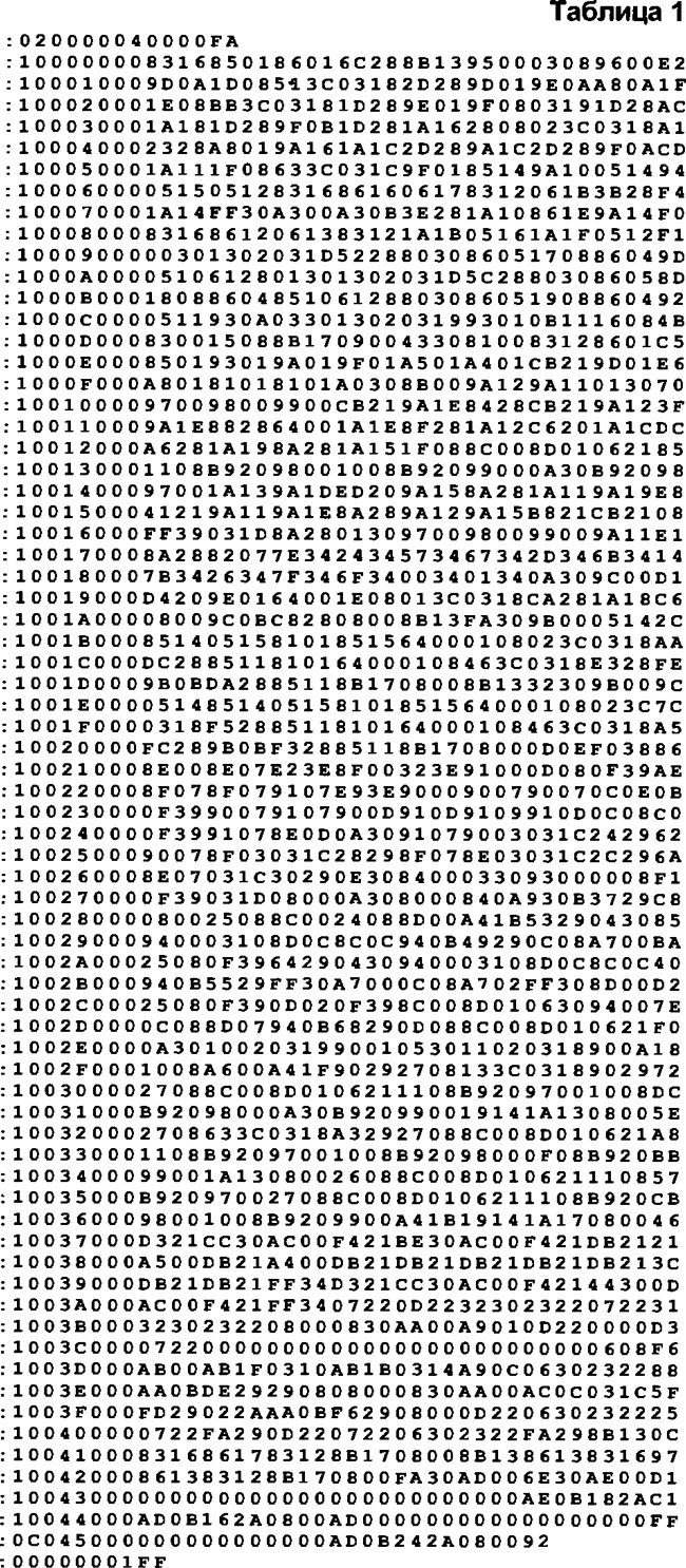
(click to enlarge)
When you press the SB1 short beep and the indicator you receive the time remaining before the beep or 0 (in the low-order), if the time in the timer has not been set. The desired shutter speed time (within 1 …99 min; injected by pressing the SB2 (without releasing SB1). In this case the indicator will automatically start to increase with a frequency of 2 Hz. Upon reaching the desired value of the button is released. Return to the temperature readings are 1 second after releasing the button SB1. On after the preset time for 10 seconds emits an intermittent the audio signal a frequency of 1500 Hz.
In table. 2 shows the codes of the firmware of the MC, giving the described device function control thermostat maintains desired temperature in a controlled environment with an accuracy of ±1 °C.
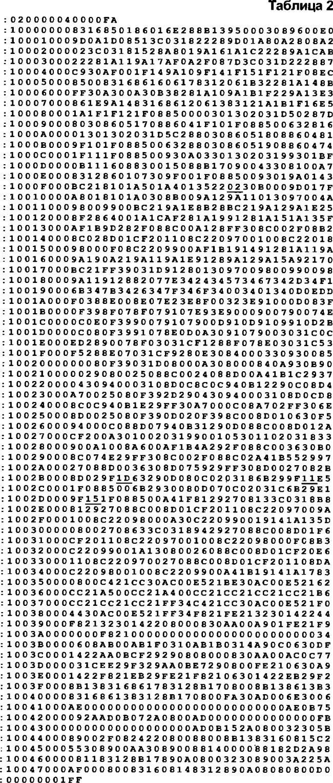
(click to enlarge)
Viewing and setting the temperature (in the range -54 to+124 °C) are as in the previous case, using the buttons SB1 and SB2. Temperature setpoint stored in nonvolatile memory data MK and loaded it with every power on of the device to the network.
When the device with the thermostat signal to control the heater or the refrigerator compressor is removed from the output RA3, instead of a cascade transistor VT1 is set optimizarea relay that controls the power actuators or contactors, which, in turn, connects the heater or the compressor to the mains. Diagram of a possible variant of such relays it is shown in Fig. 2.
Are shown in table. 2 "firmware" MK is designed for control of heating element. For example, if the set temperature on the thermostat is equal to +30 °C, the output RA3 MK the alarm log. 1 (corresponds to turning on the heater) when the temperature controlled environment below +29 °C, but as soon as the temperature rises up to +31 °C, the heater will be disabled. Thus, hysteresis between the on and off of the heater is 2 °C., For his the value of "responding" the first underlined byte (02) in the table. 2: if it is to replace "01", the hysteresis is reduced to 1 °C, and if "03" will increase to 3 °C and T. D. the smaller the hysteresis, the more accurate will be maintained at the set temperature in controlled environment, but more often will be repeated cycles of on-off actuators, and Vice versa.
When controlling a compressor of a refrigerator of the signal log. 1 at the output RA3, including the cooling system should appear if the temperature exceeds the specified limit, and to change the level of the log. 0, as soon as the temperature drops below specified limit, again taking into account the hysteresis specified by the value of the first the underlined bytes in table. 2. To implement this mode of operation is underlined 2, 3 and 4th bytes of the table need to be replaced respectively by "19", "15" and "11"
Source code
When programming the MC should specify the type of generator - HS, timers, WDT and PWRT is enabled.
All parts of the thermometer are mounted on the PCB of bilateral foil fiberglass (Fig. 3).
The fee is designed to install the resistors MLT, capacitors CD (C1, C2), K73-17V with a rated voltage of 400 V (C3), km( C7) and K50-35 (the rest). To reduce the size of the device details establish on both sides of the Board (where indicated by their reference designators). In the holes of the pads marked in the drawing adjacent the point at mounting solder a wire jumper (their function is performed by the output capacitor C7). Three-digit led indicator HG1 assembled from three one-bit LSD3212-20 (green glow) and may be replaced by any other input current 20 mA per element (segment). Before replacing the conclusions of the 12 indicators is cut in close proximity from the hull.
Integral stabilizer 78L05 (DA1) is interchangeable with any other voltage stabilization +5 V. Audio primer-emitter HA1 - with any compact winding resistance 8…25 Ohms (the author used an EMP emitter NSA).
If you intend to use the thermometer in harsh climatic conditions, oxide capacitors C5 and C6 should choose extended temperature range (with the marking "+105°C" or higher), and the MC PIC16F84A - execution of E/P, denoting that this chip can operate at the temperature from -40 to +125 °C. the Mounted charge of the thermometer in this case placed in a sealed plastic case and fill with sealant (for example, epoxy resin). Holes for buttons on the inner side piece stick thin rubber, and then on both sides of the resulting rubber membrane over buttons SB1 and SB2, paste plastic mugs in diameter, slightly smaller the diameter of the holes in the housing. This ensures complete isolation components of the device from the external environment. When using the device in normal conditions sealing can not do.
Place the temperature sensor inside the thermometer, as it is will lead to increased measurement error (due to the heating elements) and the inertia of the thermometer when the temperature of the environment. One of the constructive solutions - placement of the sensor chip inside glass ampoules from medicines suitable size. The flexible cable from the ampoule and from the body of the thermometer carefully pour sealant. The length of three-core cable can be from a few centimeters to tens of meters.
Collected from undamaged parts and without error in mounting the device in establishing not needed.
Author: Sergei Koryakov, Shakhty, the Rostov region.