


")

This digital instrument has two switchable sensor and in turn allows to control the temperature of the air inside and outside. Large bright led indicators enable the user to obtain information about the temperature both day and night.
The device (Fig. 1) is made on the basis of analog-to-digital Converter (ADC) CRUE - DD3 [1]. The temperature sensors are specially designed for this purpose integrated circuits KEM - DA1. DA2 (2). These chips can be considered as Zener diodes low differential resistance (<1 Ohm) and the voltage stabilizing proportional to absolute temperature. Operating current through them (about 1 mA) is determined by the resistors R1 and R2.
(click to enlarge)
The sensors are selected by the keys on the elements DD2.1 and DD2.3. run the multivibrator on-a-chip DDI and the switch SA1. In position "P" (premise) this switch at the input of the element DD1. 1 there is a low the logic level at the exit of the element DD1.3 - high. The last key opens the DD2.3, and the input of the ADC 31 DD3 signal from the installed in the housing thermometer sensor DA2. In this case, the thermometer indicates the temperature inside of the room.
High logic level from the output of the DD element 1.3 also opens the key DD2.4 and the voltage received at the pin. 2 and 6 indicator HG1, lights it segments a and with the constant segments b, C and f they highlight on the indicator letter TT.
If the switch SAJ is in position "I" (street), opened on the keys the elements DD2.1. DD2.2 and the voltage at the ADC is fed with sensor DA 1. installed on the street. The indicator HG1 is displayed with the letter "Y".
In the middle position of the switch SA1 is running multivibrator DDI and to the input 31 LCP turn 2…3 connect the sensors DA1 and DA2. Synchronously with them connecting the indicator HG1 displayed the letters "U" and "P".
So that when the temperature On the thermometer readings were zero, the input of the ADC should signal the level of which would be equal to the difference between the voltage on the sensor and reference voltage 2,732 In [2]. This voltage must be maintained with high stability and temperature coefficient voltage (TKN) built-in chip KRUA source is too large. For this reason, in the described device as a source of reference voltage used chip DA5 KREN [3]. with very small TKN.
This chip performs the functions of an adjustable precision stabilization of the throne. The required voltage 2.732 is set In a trimming resistor R10, and operating current through the chip and the divisor R10R 11 (about 6 mA) is set by the resistor R12.
The measured temperature of 100°C corresponds To the voltage between the inputs +Uuk, (vyv. 31) and-Uuu. (vyv. 30) ADC DD3. equal to 1 V. And indicators HG2 - HG5 flashed the signs 100.0 on inputs +iobr (vyv. 36) and-iobr (vyv. 35) ADC DD3 must submit an exemplary voltage of 1 V. It is removed from the engine trimmer R14.
The frequency of the generator 50 kHz ADC selected from standard range [ 1] and set elements C12 and R16. The values of the elements of the integrator R17 and C13 and capacitor correction of zero C14 correspond to a given oscillator frequency and magnitude reference voltage of 1 V. the Capacitors C1 and C2 protect the sensors from interference, and C4 eliminates the generation of the internal voltage reference -2.9 V.
To specify the sign of the measured temperature (and optionally the first digits "1") indicator is set HG2. Through its horizontal element with constantly the current flows. specified by resistor R18. As a result this element glows and forms the sign of the polarity of the voltage supplied to the inputs +Uвх and-Uвх ADC. the opposite of normal, so at zero temperature at the output 9 of the first discharge ADC there is a low logic level, which includes two additional vertical elements d and e of the indicator HG2. which generates the " + " sign. Figure "1" turns on the indicator HG2 only when the measured temperature is or exceeds 100°C.
The voltage of the whole device (-9) stable stabilizer chip DA4 (4). To power the indicators HG1 - HG5 voltage -5 V. formed by the stabilizer DA3. In Fig. 1 shows voltage with respect to the upper circuit power wires.
All items except sensor DA1, switch SA1 and transformer litany (not shown) mounted on single-sided PCB size 85x105 mm foil fiberglass with a thickness of 1 mm (Fig. 2). Dashed lines show the mounted conductors, they can be run in the form print tracks on the second side of the Board.
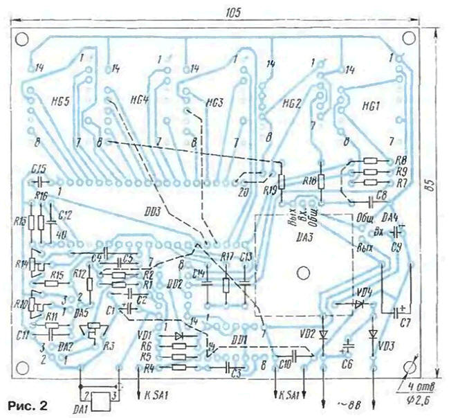
When installing mainly used resistors MT and MLT. REESE. R15 is C2-29V, but they can pick from among a MT or MLT with an accuracy of 1…2 %. As for capacitors used small domestic foreign counterparts K50-35; C5, C13, C14 - K73-17, the rest - km-5, km-6. Trimmer resistors - SDR-19a. The switch SA1 - small toggle switch with the middle position PT-2B. Chip CAM (DA1, DA2) can be replaced by LM335. and KREN (DA5) TL431 or LM431. Chip DA3 and DA4 - any integral the stabilizers voltage -5 V respectively (for example, CREB. KREN or import M.7905 with any prefixes and suffixes) and -9 In (for example, CRS. CREA, CREB, CRE,79L05,M.7909 [4]). Chip DA3 mounted on a finned heat sink dimensions 25x25x10 mm.
Indicators - import with character height of 20 mm and a large brightness when the current through the element 5 mA - this current provides chip CREW. In as HG1, HG3 - HG5 suitable indicators HDSP-3901 firm Hewlett-Packard, uniform clearance HD3P-3906 (HG2). You can also apply and any indicators with a common anode and sufficient brightness at the specified current. From domestic - are indicators of a red glow with a character height of no more than 7.5 mm - ALA-ALG, ALA - ALA. ALSO, ALSB, ALSO. ALSB. In place HG2 is permissible to set the indicator ALSO. In the absence of a specialized indicator to indicate the sign of the temperature and per-.howl numbers "±1" can to use the normal semielemental indicator. In this case, the sign "+" is not indicate, and for sakeepintouch element of the indicator. Connecting the inputs +and Uвх - Uвх chip 003 (pins 31 and 30) to the rest of the device will have swap.
The fee is placed in a housing made from organic glass, front wall - color transparent. In the upper and lower walls of the drilled maximum the number of ventilation holes with a diameter of 6 mm.
Sensor DA1 is connected to the thermometer shielded wire (the screen must be is connected to the positive output of con concentration capacitor C1) length of 5 m. It must sealed by epoxy resin, by placing the cut in the metal tube, and set on the Northern outer side of the house under the eaves of the roof so that it not exposed to direct sunlight.
As the power transformer used network adapter RW900 [5], which removed all unnecessary elements. Series with the primary winding transformer resistor MLT-2 resistance 1 kω. The resistance clarify with that. to the voltage on the capacitor C9 was $ 20…22 q also use any transformer with a voltage in the secondary winding 7,5…8 V At a current of 150 mA.
Adjustment thermomete simple. Placing the sensor in DA1 melting snow or ice (but not in ice water), a trimming resistor R10 to achieve zero indications on the indicators when installing the switch SA1 in position "I". Further, the sensor immersed in water, heated to 30…40X. the water temperature must be monitored with an accurate thermometer. Then a trimming resistor R14 you must install the appropriate indications on the indicators.
In conclusion, you should move the switch SA1 in position "P" next to custom thermometer in the enclosure to the wall space to hang exemplary thermometer and after 20…30 min trimpot resistor R3 to achieve their equality testimony.
Temperature measurement range -40…+40°C, the accuracy is mainly determined calibration, the maximum achievable value of the order of ±0.2°C.
Literature
Author: S. Biryukov, Moscow