Sometimes there are situations when it is necessary to stabilize power in the load, the resistance of which varies over time in a wide limits. In such cases, the proposed power control, which functions both as a stabilizer.
The majority described in the Amateur literature of power regulators work or with a purely resistive (incandescent, electric cookers, electric), or with an active-inductive loads (motors). However, this load either constant (electric), or changes within a relatively short the transition and then tends to a steady value (the lamp bulb, motor). In both cases, regulate the power of these loads of changes in the average current flowing. Since the load power PH, the current through IR and the resistance RL connected to the PH dependence=N·rn. when constant resistance power control is definitely achieved regulating current.
There are also such types of loads, the resistance of which depends on various factors and therefore varies in time by unknown in advance to the law. An example of such load - electrode boiler in which working environment and electrically conductive fluid is water. Water resistance depends on the type and quantity of the contained salts, temperature, speed the flow through the boiler and other factors. The resistance of the load can to change dozens of times. In this case, the control current through the load is not solves the problem of power control, since its resistance is variable. Here is the current through the load depends not only on voltage on it and its resistance. It is not possible to control the power of a common way (by setting a certain value of current). Even current stabilization not will be the way out.
Since the voltage at the load u n its capacity PH=u n·I n to stabilize power in the load must be stabilized work u n·I n, i.e., to provide his constancy. The controlled variable (the independent variable) can be voltage, since its value depends on the current, and load power.
Therefore, we need to regulate the voltage at the load, so that when the change in resistance was ensured constant average power in the load. In order to determine the instantaneous power multiply the instantaneous the values of voltage and current in the load. This follows from the classical definition of power in electrical engineering.
Block diagram of the device that implements the above-described control algorithm, presented on Fig. 1.
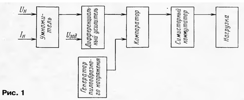
The inputs of the multiplier are served electrical signals, proportional to the instantaneous values of voltage and current in the load. Output multiplier signal proportional to their product (i.e. power), after his averaging in time is supplied to a first input of the differential amplifier, a second input filed which sets the voltage. In the differential amplifier there is a comparison voltage and the gain difference signal (error signal), which is then fed to a comparator. To the second input of the comparator serves the ramp pulses, following with twice the mains frequency. The output comparator formed rectangular pulses, the duty cycle of which determines the voltage output from the differential amplifier. The pulses from the output of the comparator control a triac switch, and that, in turn, load. When the deviation of power in the load value set by the voltage of the Inferno, the signal the error from the output of the differential amplifier will affect the comparator so that changing the pulse ratio will stabilise power.
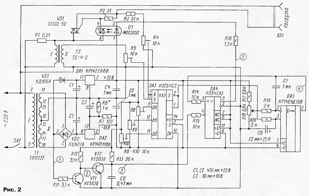
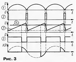
Consider the stable power regulator according to his principal the diagram (Fig. 2) and time diagrams (Fig. 3).
(click to enlarge)
The X and Y inputs of the chip DA3 (integral multiplier signals) are received signals proportional, respectively, to the instantaneous values of voltage on the load and current through it. A signal proportional to the instantaneous value voltage, remove from engine tuning resistor R4. Resistor R1 - sensor the load current. The voltage from this resistor is fed to the primary winding the step-up transformer T2 (the ratio is about 40). The need for the use of a transformer is determined by two factors. First, it increases the voltage supplied to the input of the multiplier, and secondly, provides galvanic isolation. Signals proportional to the current and the voltage - variable, but straightening is not necessary, as chip CPS (DA3) allows the fed to the inputs X and Y of the AC voltage amplitude to 10.5 V.
Note that the signals of voltage and current supplied to the multiplier should be common-mode, which is achieved by appropriate connection of the transformer windings T2.
Integral voltage multiplier CPS developed for the implementation of a number standard functional dependencies (multiplication, division, squaring, taking the square root). To perform these functions with analog signals using the exponential dependence of the collector current of the transistor from its voltage base-emitter. A maximum multiplying error of no more than 1%. More detailed information about the structure and application of integral multipliers can be found in [1].
When you enable integrated multiplier as shown in Fig. 2 the diagram at the output Z has a voltage Uz≈0,15 UxUy, where Ux, Uy - the voltage applied to the X and Y inputs of the chip DA3, respectively.
The control pulses of the triac VS1 comes from the output of the voltage comparator DA4. Integrated comparator CSS used in power control, has open collector output with a current capacity load up to 50 mA. Output the transistor is open (i.e. at the output when the load is connected the voltage is low level), if the voltage at inverting input (pin 4) of the chip DA4 more than noninverting (pin 3). At the opposite of the stress ratio on the output of the comparator will be high voltage.
The comparator DA4 compares the sawtooth voltage (Fig. 3, figure 3) and the voltage taken from the output of op-amp DA5 (figure 4).
The sawtooth generator is made on transistors VT1, VT2. It generates pulses at 100 Hz, synchronized by the mains voltage. The voltage VD2 rectifier bridge (Fig. 3, figure 1) is supplied to the base transistor VT1. The majority of the time the transistor is open, and in the moments when rectified voltage approaches zero, it closes. On his header formed short rectangular pulses (Fig. 3, figure 2), which are fed to the base of transistor VT2. Until the voltage on the base is zero, the collector of the transistor is formed by increasing the voltage (the capacitor C6 is charged via the resistor R13). At the time of occurrence of the positive pulse at the base of the VT2 transistor is open and the voltage at its collector decreases almost to zero (Fig. 3, chart 3).
The output of the comparator formed rectangular pulses (Fig. 3, figure 5). Load comparator - resistor R16 and the led of the optocoupler U1. When the current flows through the led of the optocoupler her triac is opened, allowing the opening triac VS1 - current begins to flow through the load connected to the jacks connector XS1. Changing the duty cycle of the pulses at the output of the comparator leads to the change in voltage and, hence, the power in the load. From time charts it is easy to determine that the increase in voltage at the output of op-amp DA5 reduces the power in the load.
Now the purpose and operation of the chip DA5, performing the functions the differential amplifier or the amplifier of the error signal (see Fig. 1). Specifies the voltage of the Inferno is removed from the engine, variable resistor R18 and served on the inverting input of op-amp, non-inverting input of which receives the averaged the output voltage of the multiplier DA3. The averaging of the output signal the multiplier provides an integrated circuit R20C8.
Oh DA5 enhances filed at its inputs the signals, providing equality of values the voltages on them. This means that the reduction of the setpoint voltage will lead the Inferno to decrease the voltage at the output of op-amp. Obviously, the lower according to the scheme position engine variable resistor R18 will correspond to a zero value of the power in the load. Capacitor C7 provides stable operation when exposed to the OS interference.
The power elements of the power control performed on two integral voltage stabilizer DA1 and DA2. The use of two different types of chips due to the desire to do network transformer with one secondary winding (albeit with a branch of the middle) and one rectifier bridge.
The VD1 diode eliminates the influence of the filtering capacitor C1 to the shape of the rectified the voltage applied to the input of the sawtooth generator.
The power regulator is assembled on a printed circuit Board from bilateral foil fiberglass. Drawing of the PCB shown in Fig. 4.
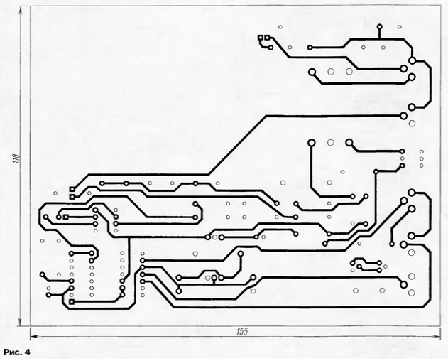
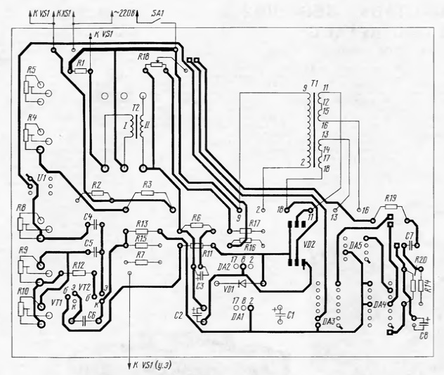
In the holes square pads, you need to insert pieces of tinned wire and solder them on both sides of the Board. Circuits DA1, DA2 installed on a small aluminum heat sinks with an area of 20...30 cm2 each; triac VS1 installed on a standard cooler (molded heat sink of aluminum alloy) brand 0231. The resistor R1 is made of Niro-pound wire with a diameter of 3 mm.
In place of the comparator DA4, except as provided in the scheme, you can also use K521SAZ, K521SA5, K521SA6 (last IC contains two Comparators in a single the body), however, you have to adjust the drawing of the PCB. Oh CRUD replace chips COD, COD, COD and all similar. Analog multiplier voltage CPS valid replace with CPS any letter index, but also correction of the PCB. Transistors VT1, VT2 - any of the series KT315, CT, CT, CT, KT3I02 or CTA. The optocoupler imported MOS you can replace domestic AOA-AOW with correction of the PCB. Triac VS1 can be applied from the series TS, TS, TS, TS with allowable pulse voltage in the closed state no less 400 V and current in the open state corresponding to the maximum load current. Diode KDA (VD1) will replace any of the series CD, CD, CD.
Rectifier bridge (VD2) - any of the series KTS402, KTS405, with correction of the PCB. Oxide capacitors C1 - C3, C8 can be K50-16, K50-35, K50-24, K50-29; C4, C5, C7 Km-6, K10-17, K73-17; C6 - K73-17, K73-24, C-P2 (this capacitor should have small TKE). Trimmer resistors R4, R5, R8-R10 - SP5-2, SDR-19, SDR-38, variable resistor R18 - SP-0,4, GPA-4, GPA-16, SDR-30, others - MLT, S2-23. The transformer T1 is TPP. It can be replaced by any other, which the secondary winding with a branch of the middle 33 provides a voltage 40 V and... with a current capacity of at least 150 mA. The transformer T2 may be any other with a conversion ratio of 30 to 50. The power switch SA1 - automatic switch A3161, HE or AP50. In addition, it performs the function fuse.
Establishing power control start with checking the output voltage chip DA1 ( + 15 V) and the output voltage of the chip DA2 (-15 C) resistor R6. Then produce the adjustment of the voltage multiplier DA3. For this purpose, the inputs X, Y, output Z, and pin 1 is disconnected from the other elements. Engines trimmer resistors R8-R10 is set to the middle position. On input X set voltage +5 V, and the input Y - O V. a Resistor R9 sets the output the voltage multiplier Of V. Then X input set voltage O V, and the input Y- +5 V. Resistor R8 sets the output voltage Of V. Then on both inputs the multiplier serves voltage of + 5 V and measure the output voltage. Then on one of the inputs changes the polarity of the input signal (i.e., serves -5 V), and again measure the output voltage. Resistor R10 are making to two the last value of the output voltage are equal in absolute value (on the sign they should be the opposite). If necessary, repeat adjustment. After that, connect the inputs and the output of the voltage multiplier to the elements controller. Engines rigged resistors R4 and R5 to establish a middle, and the variable resistor R18 is at the bottom according to the scheme position.
Connector XS1 connect load and supply power to the power controller. Smoothly the rotating axis of the variable resistor R18, make sure to increase the voltage load. If the voltage at the maximum load in any position of the engine the variable resistor R18, the reason for this may be incorrect phasing the windings of transformer T2, leading to the flow-of-phase voltages to the inputs X and Y chips DA3 and negative voltage at the output Z. In this case you should swap any of the conclusions of the windings of transformer T2.
Trimmer resistors R4 and R5 are making to the maximum (amplitude) the voltage values at the inputs of the multiplier does not exceed 10 V. This is useful be monitored with an oscilloscope. In a pinch you can use the AC voltmeter. With sinusoidal voltage at the load (this occurs when the triac VS1 opened at the beginning of each half period, and the voltage across the load in this case is almost equal to the network) effective the voltage at the inputs of the multiplier should not exceed 7 V. Regulation power should be gradually implemented throughout the interval of the rotation axis of the variable resistor R18. If the upper circuit on the position of the slider of the variable resistor R18 at maximum connected load, the voltage across it reaches the values of the network, decrease the resistance of the resistor R17 to 2.2 kω or reduce the transmission of current and voltage by moving down under the scheme the engines of trimming resistors R4 and R5.
To check the function of the power stabilization must be loaded with a variable resistance (it is convenient to use two-piece household heater) and laboratory autotransformer appropriate power. Load must be active (i.e. not having inductive or capacitive component).
The power controller is connected to the network through an autotransformer and connected to the output of the controller one section household heater. Autotransformer set the voltage of 220 V. by Connecting in parallel with the load voltmeter AC, which measures the effective value (quadratic voltmeter), variable resistor R18 mounted on the load voltage 150...200 V. Then connect another section and again measure the voltage at connector XS1. It should be reduced by 1.4 times [2]. In another variation of the resistance loads in either case, you will be equality Uн2/RL = const. If the load resistance will increase so that to maintain the established power voltage to exceed its maximum value, the controller exit power stabilization.
The power controller has stabilizing properties not only in terms change the load resistance, but also in relation to fluctuating network voltage. You can verify this by changing the supply voltage of the regulator with by using an autotransformer in the range of from 190 to 240 In (of course, the load is connected). The voltage at the load when the change of the supply needs to be stable. To vary the opening angle of the triac VS1, as can be seen with an oscilloscope. Signal can be removed with either the load, or the output of the comparator DA4.
If there is no ham voltmeter, which measures current value (for example, the device of an electromagnetic system), it is possible to measure the power use induction electricity meter: the number of revolutions of the disk the counter must be constant when you change the load resistance and unchanged the position of the slider of the variable resistor R18. To use the voltmeter mean straightened voltages for these purposes, impossible.
To improve the reliability recommend consistently with optimistion to include a resistor of about 150 Ohms.
Literature
Author: A. A. Evseev, Tula


