The article is devoted to the selection and implementation of electronic practice machines that are designed to maintain the required temperature in different household devices. The author's recommendations can be useful to many the radio fans designers.
The scope of the stabilizers of the temperature in the devices used in the household, rather wide. This, for example, storage of vegetables, aquariums, small incubators, heat processing chamber bees, greenhouses and much more. Design of thermal stabilizers for various purposes, the description of their the work is an extensive literature. And yet this theme, in my opinion, remains relevant, especially for those who decide to build such device. Given the difficulties associated with the acquisition of a number parts, and various conditions of operation of the stabilizers, I would like before description of specific designs to highlight some General issues.
First of all, proceeding to design heat stabilizer, it is necessary to determine the capacity of the heater, providing the desired temperature in a given volume. This is a separate, often complex task that requires thermal calculations. To approximate the same calculations you can use simple formulas. For example, for freeze protection in your products growers when the outdoor temperature to -30°C in the box, made from boards or chipboard 20 mm thick, with a layer of foam thickness 25...30 mm, the required power of the heater should be such as specified in [1]: P = V2/3, where P is the heater power, expressed in watts, V is the internal volume of the box in litres.
For balconies, frame greenhouses with a coating of glass or polyethylene required the total capacity of the heater is determined by the following formula [2]:
P = 1,23·SN·CT (TVN - tнap),
where P is the heater power in watts; SN - total surface area cooling (walls, floor, ceiling) in m2; CT is the heat transfer coefficient in W/m2 °C; TVN and tнар respectively indoor and outdoor temperature display in degrees. The value of the coefficient Kt can be from CT = 3.3 V (for double glazing) to CT = 7,5 (for single-layer plastic film).
Any stabilizer temperature includes sensing element sensor temperature and amplifier sensor signal; a comparison device signals or comparator; an electronic key that performs the functions of Executive devices; the power supply and the heating element.
As the temperature sensor is usually used thermistors series KMT, MMT, PT, temperature coefficient of resistance (TCR) which is negative - 2 7... % / deg. and varies with the temperature, and the tolerance value the resistance of the thermistor is 10...30%. In Amateur the thermistors thermal stabilizers are used most often due to the large TCS. However, their essential nonlinearity and large tolerances require an individual adjust design thermal stabilizers, calibration of scales, hampers replacement in case of repair.
Calculation of parameters of the bridge with semiconductor thermistor, at elevated the accuracy requirements set forth in [3, 4].
The best metrological characteristics have temperature sensors series TSM - copper. Their ambition is positive, but is only 0.3 % / deg.= = 1/293°, moreover, the linearity is ensured in a wide temperature range. They are instruments of high accuracy class (0.1...0.5 %) and can work even in aggressive environments. The drawback of FCM is relatively large length (about 300 mm) and high cost.

Less well-known as the silicon diode temperature sensor, a negative coefficient conversion equal to 2 mV/deg. [5, 6]. Almost any low-power silicon diode will provide a linear transformation of temperature into voltage.
Any of these converters typically include in one of shoulders of a resistor bridge, a power supply which is stable. Output the bridge signal is fed to the input of the comparator or, if necessary, pre-amplify. For comparison of signals is more convenient to use the comparator representing an operational amplifier (op-amp) with a positive feedback. The comparison function can perform any OS series C, or C specially designed Comparators series C. The most preferred the comparator CCS providing output current to 50 mA, additional amplifier directly to include electromagnetic relays actuating mechanism.
The choice of type of relay is determined by two factors - the value of the current positives and allowable voltage and current, its switching contacts. When the voltage is 220V, the relay contacts must be reliably commutate current heater. The most common low-power relay - RES, REN [7]. Winding of the relay RAN and MCM-48 (passport 4.509.146) is designed to work directly from the mains AC voltage of 220 V, the maximum acceptable current contacts 5 A, which in practice allows to use them in most cases. For parallel connection of two groups of contacts of these relays ensure the inclusion heaters with a total capacity of up to 2.2 kW. In addition to the electromagnetic relay, element Executive device that includes a heater, may be SCR or the triac.
These devices allow switching current of the heaters up to 80 A. the Lack of contacts makes their use preferable. However, the construction itself heat stabilizer becomes more complex than with electromagnetic relays Executive link.
The PSU heat stabilizer is usually a transformer, stepdown the voltage to 13...16, with one or two rectifiers and protozoa the rectified voltage stabilizers. The power transformer usually does not exceed 10...15 watts. You can use unified transformers series the chamber of Commerce, having your own set of secondary windings [8].
As a source of heat, especially from the standpoint of electrical safety, it is better just use tubular heaters - Teng; fit, of course, and conventional incandescent lamps designed for a voltage.
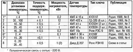
Today there are many circuit design-build thermostabilizers in which these elements are combined in various combinations. To guide in the selection of the design temperature stabilizer you can use offer here a table which shows the main some technical data thermal stabilizers, previously published in "Radio".
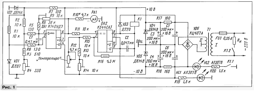
At the same time propose to repeat the thermal stabilizer wide application (Fig. 1), in which the temperature sensor is a silicon diode or copper resistor. Another difference of this variant of electronic machine - the absence transistors and the presence of a microammeter to measure the temperature.

(click to enlarge)
Like most thermal stabilizers indicated in table, it consists of four nodes: a sensitive element, comparator, actuator and AC adapter. Temperature sensor, the function of which performs diode VD1 included in the measuring bridge with the resistors R1 - R4 in the other three it shoulders. The signal output from the bridge is fed via the resistors R5 and R6) on both inputs the operational amplifier DA1 covered by negative feedback (chain R8R9), and with its output to the inverting input of the comparator DA2. Necessary the temperature in a closed volume set variable resistor R12, supplied with an appropriate scale.
The function execution unit executes the electromagnetic relay K1. Actuating the output signal of the comparator, the contacts K1.1 relay include led HL1, signaling turning the heating on, and the contacts K1.2 - heater (RL).
The power supply form a transformer T1, bridge rectifier VD6, smoothing filters C5R17 and C6R18. Zener diodes VD4 and VD5 provide circuits device bipolar supply voltage of ±10 V.
For visual control of air temperature in the heated volume in the device introduced microammeter RA1 on current full deflection 100 µa (M), scale which programfrom-in degrees. If the electronic part of the device located outside the heated volume, the diode detector (VD1) is connected to resistive bridge with shielded wire.
When indicated in Fig. 1 chips, resistor values, and other details the device provides temperature stabilization in the range 0...20°C. For the stabilization temperature of up to +36... +45°C, are required to incubator, the nominal resistance of the resistor R13 should be 2 ohms.
All fixed resistors used in heat stabilizer, - MLT and variables - SP5-2 (R4, R9 and R14), PPV-40 PPB or (R12). The capacitors C3 - C6 - oxide K50-6, K50-16 or K50-29, and the rest - km-5 km or 6 of them. Diode bridge replace CCA the Assembly KTS402 with any letter index. Zener diode VD2 is the voltage stabilization 8...8.5 V, a, VD4 and VD5 - 9.5...10,5 V.
Relay K1 - RAN (passport RH.564.509) or MCM-48 (passport 4.500.232).
Temperature sensor VD1 - any silicon. Better, however, in metal case series D D226 or with any letter index, such as the diode has a lower thermal inertia.
The power transformer T1 of the power supply unit is about 5 watts. Its secondary the windings must provide the AC voltage 2x12 In load current 80...100 mA.
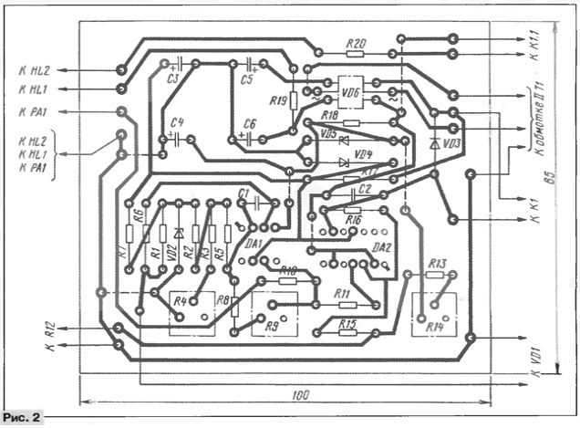
The heat stabilizer is mounted in body size 170x90x60 the Most part mm. its details are located on the PCB size 100x85 mm (Fig. 2), made of one-sided foil fiberglass. Transformer T1 and relay K1 are mounted separately, and microammeter RA1, variable resistor R12 and LEDs HL1 and HL2 placed on the front panel of the housing.

Calibration is best done in this order. Diode VD1 place in an environment with a temperature corresponding to the lower limit control (0°C), and to balance the bridge resistor R4. The readings microammeter should to be zero. Then the temperature of the diode to increase to a maximum value (20°C) and resistor R9 to achieve the maximum deflection of the microammeter to 100 mA.
Next, you need to adjust the operation of the comparator DA2. For this engine resistor R12 is set in the extreme upper circuit position, and the diode VD1 is heated to the maximum temperature (20°C). A trimming resistor R14 achieve switching of the comparator to a different state, the relay K1 and sunbathing LEDs HL2. This division is on the scale of the resistor R12 will be to correspond to a temperature of 20°C. Then, without changing the resistance of the resistor R14, graduate scale of the resistor R12 at several points, achieving actuation comparator for different values of the temperature diode sensor VD1.
If the temperature sensor uses a copper resistance thermometer, TKE which is positive, in the measuring bridge includes in place of the resistors R3 and R4, and the resistor - diode VD1. The procedure for fitting the lower and upper the range of temperature remains the same.
If the electronic part of the thermal stabilizer is out heated volume, the Zener diode VD2 to improve the accuracy of the device you should install temperature-compensated, for example, series D or KS191.
Literature
Author: Y. Andreev, St. Petersburg


