Trinistorny power controllers with phase control repeatedly described on the pages of our magazine. But unfortunately, many of them are strong sources of electromagnetic noise, which limits the scope devices. Foreign domestic regulators are supplied built-in interference suppression filter. Moreover, the level of any noise emitted must to meet stringent standards in the country. One of such regulators and tells the author.
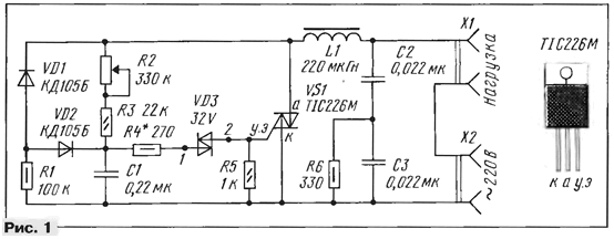
The power control circuit with phase-pulse control is shown in Fig. 1. It assembled by the classical scheme on symmetric diacs 32V (VD3) and the triac TIC226M (VS1). In each half-wave of the mains voltage the capacitor C1 is charged by current flowing through resistors R2, R3. When the voltage across it reaches 32, dinistor is opened and the capacitor C1 is quickly discharged through resistor R4, a dinistor VD3 and the control electrode of the triac. Thus, control of the triac occurs in quadrants I and III: when the voltage at the conventional anode of the triac (upper circuit output VS1) is positive, managing momentum is also positive, and negative voltage is negative polarity.

The value of the power in the load connected to the connector X1, depends on what long the triac will be turned on during each half period of the mains voltage. The moment of switching on of the triac is determined by the threshold voltage diacs and the time constant (R2 + R3)C1. The more resistance you typed the variable resistor R2, the longer the period of time during which the triac is in the closed state, the lower the power in the load. Indicated in the diagram, the component values provide a time constant almost complete control range of output power from 0 to 99 %.
To achieve a sufficiently smooth regulation of output power, AC resistor R2 should be with feature group B. Suitable resistor group In, but then it would have to be included so that an increase in output power (i.e. with the decrease of the resistance of the variable resistor) occurred when rotating the handle counterclockwise.
The circuit formed by the diodes VD1, VD2 and the resistor R1 ensures smooth adjustment at minimum power output. Without her characteristic control the controller has a hysteresis. For example, the brightness of the filament lamp used as the load, increasing the power output changes abruptly from zero up to 3...5% of full brightness. The essence of this phenomenon consists in the following. If high resistance of the resistor R2 when the voltage on the capacitor C1 is not exceed 30 In, dinistor't open during the entire half cycle network voltage and output power equal to zero. By the time of the transition network voltage through zero, the voltage at the capacitor has a value of zero and following halftime, a significant portion of time the capacitor is discharged. If the resistance of the resistor R2 to reduce, after the voltage on the capacitor will begin to exceed the threshold dynistor, the capacitor will be discharged at the end of halftime and in the next half cycle will begin immediately be charged, so in the new half-cycle of dinistor will open earlier. The diode-resistor chain discharges the capacitor during the transition network voltage from negative to positive half-wave and thus eliminates the the effect of the abrupt initial power increase in the load.
Resistor R4 limits the maximum current through the dinistor to about 0.1 A and slows down the process of discharge of the capacitor C1. Thus a relatively large pulse width, sufficient for a safe start triac VS1 even with a significant inductive component of the load. When indicated on the diagram the values of resistor R4 and capacitor C1 duration control pulse equal to 130 μs. A significant part of this time through the control electrode of the triac, a current flows, sufficient for opening triac in any quadrant for triac 32V it corresponds to 50 mA.
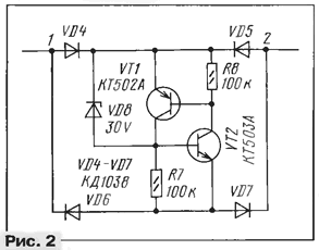
Symmetrical dinistor 32V (VD3) provides the same opening angle triac in both half waves of the mains voltage. Therefore, as described the regulator will not rectify the mains voltage, so in many cases may be applied to control the load connected to it via transformer. A dinistor 32V possible to replace its analogue, assembled on transistors of different structure, as shown in Fig. 2. Diode bridge VD4-VD7 provides symmetry control a triac, and a low power Zener diode VD8 specifies the alarm threshold of analog. Transistors VT1 and VT2 must withstand a significant (not less than 0.1 A) pulse current base. Static coefficient of transfer the base current of the transistor VT2 is at least 50. The diode bridge also needs to withstand a direct pulse current value is not less than 0.15 A. Suitable, for example, diodes series CD with any letter index.

The maximum allowable voltage of the diodes and transistors of the analog dynistor should to be not less than 30% of the voltage stabilizing Zener diode VD8, i.e. not less than 50 V. it is Possible to use two low-power Zener diode, enabling them consistently that their total voltage stabilization was 25...30 V. Resistors R7 and R8 provide the analogue of the high temperature stability work.
Triac TIC226M, the allowable current of 8 A, allows you to manage the load power up to 1 kW. For loads with power up to 2 kW can use triacs with the allowable current of 16 A. 15...
Instead of the triac TIC226M you can apply domestic SCR COG. However it has significantly worse sensitivity. For reliable operation through the control electrode of SCR COG should leak current value is not less than 250 mA at ambient temperature -60°C or 170 mA at room. Therefore, with the use of SCR COG the resistance of the resistor R4 should reduce to 100 Ohms, and the inductance of the inductor L1-100 µh. Accordingly the transistors and diodes in the analog dynistor (Fig. 2) must be able to withstand currents of up to 0.3 A.
The level of interference from the regulator, will be significantly higher. Except also, he will have less stability when working on the load the inductive component.
The voltage drop across the triac VS1 is equal to about 2 V, so under load of a power exceeding 100 W triac must be installed on the appropriate the heat spreader. At a lower load heat sink itself can serve as a printed circuit Board controller. For this triac in the housing TO should be put on foil side of the PCB, screwing his MOH screw with nut, and under the installation place of the triac to leave the area of the foil size 3...5 cm2.
In Amateur designs often instead of the triac using a diode bridge and SCR, which increases the component cost and size of the structure. This the decision about dual power losses in the regulator and narrows the range allowable loads. In addition, charging the storage capacitor occurs a single power that, as correctly noted in the article by A. Maslov again about trinistorny the power control" (see "Radio", 1994, № 5, p. 37), leads to malfunction of the regulator at low installed capacity.
Speaking about the article A. Maslova, not to mention that the proposed method reduce the rate of rise of voltage across the SCR (dV/dt) can lead to damage of SCR due to its overload current pulse at the moment of inclusion, since the discharge current of the capacitor, shunt SCR, is not limited. If you use a high quality capacitor with low internal resistance, then SCR will almost certainly be destroyed by the excess value of the of current or rate of current rise (dV/dt). To resolve this shortcoming, need in series with the storage capacitor to enable a wire or voluminous carbon resistor of at least 10 Ohms. Metal film and carbon-film resistors were inadequate, since they can leave failure due to the large instantaneous power dissipation in the moment of inclusion of SCR.
In the described power control (see Fig. 1) the rate of change of voltage naviscore VS1 is limited by the capacitors C2, C3, and the current of discharge when the opening of the triac - inductor L1. Modern triacs withstand speed voltage 50...200 V/µs, and some even up to 750 V/ μs, so the relatively small capacitance of the capacitors C2, C3 prevents false triggering of the triac even with low-impedance loads. Sadly note that the obsolete domestic series triacs have CO only 10 V/µs.
Simultaneously, the inductor L1 and capacitors C2, C3 form a noise a low pass filter. The inductor must withstand the load current without saturation of the magnetic circuit. As the magnetic core, the author used the outer ring diameter of 26.5, the inside of 14.5 and a thickness of 7.5 mm from powder with iron magnetic permeability of 75. Coil contains 58 turns of wire PEV-2 in diameter 1 mm. Such a choke suitable for use with a load capacity of up to 1 kW. When the use of SCR COG the number of turns of the inductor should be reduced to 40.
Capacitors C2 and C3 should be of type X1 or x2 (international designation capacitors), specifically intended to enable network between wires; they are in buildings made of self-extinguishing plastic, preventing fires, possible in the breakdown of the capacitors. On the body of the capacitor of this type should to be specified nominal voltage 250VAC, which applies in AC (AC = alternated current, i.e. AC). Except the housings must be present symbology test labs checked the capacitor and found him fit for use in AC. The housings are good capacitors, as the rule, dotted with such signs because they have been tested in many laboratories. In the extreme case, instead of the capacitor type X1 or x2 can apply metal foil or paper capacitor rated voltage not less than 400 V.
Author: A. Kuznetsov, Moscow


