The composition of this ASIC includes two analogue and SCR a control device. The chip is designed to work in the power regulators, some versions of which are described in the article.
As noted in article I. Nemica "Chip CPM - phase controller power" ("Radio", 1999, No. 7, pp. 44-46), this interesting semiconductor the device is able to operate at mains voltage 80...276 V and control the load power up to 150 watts at a maximum current through it to 1.2 A. On these parameters and should be guided in the design of power regulators.
For the construction of one of the power regulators, providing a smooth change the brightness of the lamps, will need, in addition to chips, four additional details: two capacitor, variable resistor, and a switch (Fig. 1). When the closed contacts of switch SA1 (i.e., when the closed conclusions 3 and 6 chips) lamp EL1 is not illuminated When the contacts are open, variable resistor smoothly control the lamp brightness is greatest she'll be on top diagram the position of the slider.
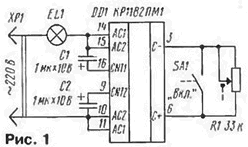
If the lamp is extinguished (i.e., the switch SA1), the chip remains under voltage, which is of course undesirable. The way out is to set in the chain one of the network cables separate switch (then the need for SA1 will disappear), and the contacts must be rated for switching used load and mains voltage.
Entering into the device another capacitor (Fig. 2) be able to get the regulator power with smooth on and off the lamp. When the closed contacts switch lamp is not illuminated. When the contacts open, charging begins capacitor C3 and the lamp will gradually light up. In the subsequent circuit contacts of the switch, the capacitor is discharged by the resistor R1, the brightness of the lamp gradually decreases. Duration of ignition and extinguishing of the lamp depends on the capacitance of the capacitor. The resistance of the resistor in the device must not to exceed specified on the schematic values.
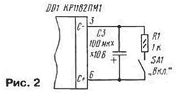
As you've probably guessed, to control the power at the load it is necessary to change the resistance between pins 3 and 6. This allows to use other solutions to the problem. For example, to connect to the specified conclusions the optocoupler diode (Fig. 3).
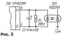
When the emitting diode of the optocoupler is energized, the lamp is not lit. Passing through the corresponding diode current, be able to install the desired brightness of the lamp. Similarly, the device operates with transistor optical coupler (Fig. 4).
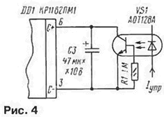
Such a construction provides a galvanic isolation between the inverter and source Manager of an electrical signal.
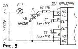
But if you want to manage a more powerful load than allow the chip? Then have to use option (Fig. 5) at which the chip will be to control the triac VS1, and it is already - load EL1 power up to kW. For management will have more power to choose the appropriate triac.
The regulator is permissible to use the automatic night lighting, setting between pins 3 and 6, the phototransistor VT1 (Fig. 6). Suitable phototransistors CTFA, CTFA, FT-1K. Any of these devices should be placed so that it is protected against include light bulbs and installing in the open air and from precipitation.
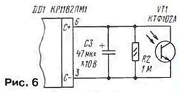
While the phototransistor is illuminated, the lights are off. But as soon as the light falls, they are turned on, the brightness gradually increases.
And yet another device - a power control soldering iron (Fig. 7). From the preceding it differs in that it uses only "half" of chip - one analogues the SCR circuit is disabled conclusions 9 - 11. In addition, diode VD1, "normally open" output circuit during one half cycle of the mains voltage. This the decision is explained by the need to adjust power heater soldering iron (resistor R1) to the extent not exceeding 50 %.
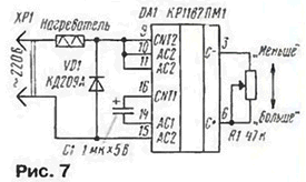
The regulator is used with soldering irons with a capacity of up to 50 watts operating voltage 36...40 V (At same voltage) or up to 150 W at a voltage of 220 V.
The diode - rectifying any with the allowable current of 0.5 A and reverse voltage of 350 In (220) or 0.7 A and 100 a (40 In).
Oxide capacitors in all devices - K50, K52, K53, variable resistors - JS4, str, SDR-VM (with switch).
The small dimensions of the parts and a small number of them allow you to put the controller, for example, in the stand table lamps, in case the power switch in the handle powerful soldering iron.
When establishing and operation of devices necessary to consider their galvanic the network connection and follow the rules of electrical equipment.
Possibilities of chip CRM very extensive, so it can also find the use of the power regulators for the heaters, the speed of rotation motors and other occasions.
Author: I. Nechaev, Kursk


