


")

The article describes two thyristor power control for inertial load. The use of microcontrollers allows you to use special algorithm uniform distribution of current pulses in the load and get high the switching frequency even when the step of regulating the power of 1 %. The first device is designed to control the power in the load, designed for mains voltage. The second works with low-voltage load, which is not galvanically connected to the network. In addition, this controller stabilizes power in the load fluctuations of the mains voltage.
For controlling the inertial load applied thyristor power controllers, working on the principle of submission to the load of several half-cycles network voltage, followed by a pause. The advantage of such devices is the moments of switching of the thyristors coincide with the moments of transition network voltage through zero, so the level of interference is dramatically reduced. In addition, such a device, unlike the regulator with phase control, does not contain analog threshold elements, which increases stability and simplifies establishment. Because switching occurs only during the transition network voltage through zero, the minimal portion of energy delivered to a load equal energy consumed by the load during one half cycle. Therefore, to reduce the step power control is necessary to extend a repeating sequence halfcycles.
For example, to obtain the step 10 %, the necessary sequence of ten halfcycles. In Fig. 1 and shows a sequence of pulses on the control the electrode of the thyristor for power at the load of 30 %.
As can be seen, the thyristor is opened the first three half-cycles, and in seven subsequent closed. This further the sequence is repeated. The switching frequency of the regulator for any power, less 100% equal to 1/10 of the frequency half-cycles.
Much more logical would be to distribute the half-cycles during which the thyristor open, if possible, evenly over the entire sequence [1]. In General if the problem of uniform distribution of any number of pulses N in sequence of length M (when N is less than or equal to M) the algorithm solves Bresenham. which is commonly used in raster graphics to build the inclined segments. This algorithm is implemented using integer arithmetic, which greatly simplifies programming. In Fig. 1,6 shown the sequence for the same power 30 %. but with the use of the algorithm Bresenham. In the latter case the switching frequency is three times higher. Should to note, that the gain is more noticeable when a small increment of power control.
The basis of power control (Fig. 2) the microcontroller DD1 ATC ATMEL [2]. To power used a low-power transformer TT. together with the use of six provides galvanic isolation from the mains. It makes the device more electrically safe. Another useful feature of the regulator - it can be used with loads that are designed for different working voltage. You only need to submit the required voltage thyristors with additional transformer. You can, for example, to feed a low-voltage soldering iron. It is only necessary that the voltage and current do not exceed the maximum allowable the values applied to the thyristors.
Regulate the power in the load buttons SB1 and SB2. A short press on one of buttons will increase or decrease by one step, and when you hold down the button the monotonous change of power. Simultaneous pressing of two buttons leads to the off load, if it was included or includes maximum power, if the load was off.
The value of the power in the load output to the led indicators semielemental HG1-HG3. To reduce the number of elements applied dynamic display, implemented in software. The cathodes of indicators connected to the ports microcontroller, anodes include transistors VT3 and VT4. run the scanning signals indicators. In the highest bit possible indexing only one, so the elements of b and C through the resistors connected to one port, and the anodes of indicators HG1 and HG2 United. The pulse current items limited by the resistors R10-R18 at about 15 mA, which is less than the maximum allowable current for ports (20 mA). but it is enough to obtain the necessary brightness.
Built into the microcontroller's analog comparator binds to the moments of transition of the mains voltage through zero. At its inputs via limiters VD5R2 and VD6R3 is supplied AC voltage from the secondary winding transformer power. The role of the limiter for negative half cycle mains voltage perform the diodes of the rectifier bridge. Switch comparator occurs in the moments of transition of the mains voltage through zero. Output comparator queried programmatically, and as soon as change is detected it status, output control thyristors (port of the microcontroller P3.2) you receive the control signal to turn it on. In the case when the current halftime shall be pass, this signal will not. Then at 4 MS is switched on indicator HG3. At this time there is the checking of the closed state of the buttons I. if necessary, change the value of the current capacity. After this shoot control voltage with thyristors and 4 MS include indicators HG1 and HG2. During the next 4 MS expected new state change of the comparator.
The signal from the port P3.2 arrives at the switch, transistors VT1 and VT2, which serves to manage emitting diodes with six. For switching load are two obliterator included anti-parallel. Their light emitting diodes connected in series. Current emitting diodes-about 100 mA is set by a resistor R1.
The controller can operate in two modes of different steps of power control. Mode select seal jumper S1. The position of the microcontroller polls immediately after the reset. In position 1, shown in the diagram, step power adjustment - 1 %. The LCD will display a number from 0 (0 %) to 100 (100 %). In position 2 step equal to 10 %. The indicator displays the numbers from 0 (0 %) to 10 (100 %). Choice of ten gradations in mode 2 due to the fact. in some cases (for example, control of the stove) small adjustment step power is not needed. If the regulator is supposed to use only in such mode, the indicator HG1 and resistors R17, R18 can be omitted. In General speaking, the device allows you to arbitrarily set the number of levels of power for of each mode. It is necessary only to program code at address N to bring the desired the gradation value for mode 1. and address UN - for mode 2. Just need remember that the maximum number of levels in mode 1 should be less than 127, and mode 2 - not more than 99, since in this mode the display of hundreds of impossible.
If the load current does not exceed 2 A. obliterator can be used without the heat sinks. At higher current they are mounted on heat sinks area of 50…80 cm'. When the load is fed by a voltage less than 50 V. obliterator can be any class (voltage). When you work as a network voltage class six should not be below 6. Transformer power - with any low the voltage on the secondary winding 8… 10 V and the allowable current of 200 mA. Diode FR157 (VD1-VD4) interchangeable on CD CD or rectifier bridge with KTS405 any letter index. Chip stabilizer DA1 7805 (domestic analogue CREA, CREN), additional heat sink is not required. Transistors VT2-VT4 - any low-structure p-n-p. Instead of VT1 transistors applicable KT815, CT with any letter index. However, it is necessary to choose the resistor R5. Diodes VD5. VD6 - any low-power silicon, for example, KD521, KD522. SB1 and SB2 buttons - any small non-locking, for example, IPP-159. Indicators HG1 - HG3-any semielemental with a common anode brightness glow. Capacitors C1. C3, C6 - any oxide, other ceramic. Resistor R1 - MLT-0,5, and the rest-MLT-0.125. Even easier to apply resistors for surface mounting, for example. RN1-12.
The regulator in establishing not needed if built from a known-good parts and the microcontroller is programmed without errors. It is advisable to check the correctness of binding to the frequency of the mains voltage. To do this to triggering the oscilloscope AC line voltage and verify that the pulses scan display (signals RXD and THO microcontroller) synchronous with the network and have twice the network frequency. Sometimes, when you connect the load due to interference synchrony is disrupted. In this case, between the inputs comparator (pins 12, 13 of the microcontroller) to enable the capacitor 1000-4700 PF.
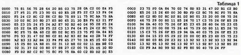
The program codes of the microcontroller are shown in table. 1.
With step regulation, 1 % voltage regulation network is the main a source of error set power. If the load is not galvanically connected to the network, it is easy to measure the average value applied to the load voltage and using the feedback circuit to maintain it constant. This the principle and implemented in the second controller. Functional diagram of the device shown in Fig. 3.
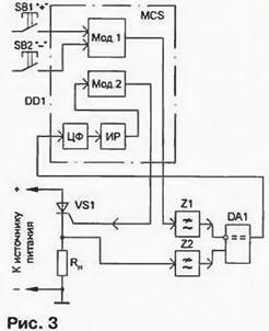
For operation in the automatic control mode use two Bresenhams modulator (Mod. 1 and Mod. 2) that are implemented software. To the first input receives the code required power asked the control buttons. At its output the pulse sequence is formed, which through the lowpass filter (Z1) is fed to the inverting input of the comparator. At its non-inverting input after the low-pass filter (Z2) receives voltage, the charge to the load. From the output of the one-bit comparator the error signal is fed to the input of the microcontroller, where it is subjected to digital filter.
Since a digital filter (CF) operates synchronously with the modulator, is provided effective suppression of oscillations at the frequency of the output pulse sequences and its harmonics. From the output of eight-bit digital filter the error signal is fed to an integrating controller (IR). To improve the accuracy integrating the controller is operating in sixteen-bit grid. The youngest of eight bit of the output code of the controller is input to the modulator Mod. 2, the output which is formed by the pulse sequence received at the office of the thyristors.
As for the circuit, a regulator is very similar to that described above, and therefore has the sense to focus only on the differences. In Fig. 4 shows a different part scheme. The remaining pins of the microcontroller DD1 not shown in the diagram. They connected as well. as in Fig. 2.
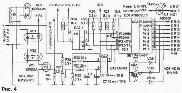
Because the available port I / o of the microcontroller was not enough, had to abandon the use of the built-in comparator. Instead the controller is applied to a dual comparator DA2. On one (DA2.1) compile a node reference to the points of zero crossing of the mains voltage. Because of the characteristics chip LM393 in this node had to add a resistor R19, which resistors R2 and R3 (see Fig. 2) forms a voltage divider that reduces the voltage of the negative polarity at the inputs of the comparator. Signal (a square wave network frequency) from the output of the comparator is input to the microcontroller P3.2.
The second comparator (DA2.2) is used in the feedback circuit. A one-bit signal the error is input to the microcontroller P3.5. The inputs of the comparator set the LPF. formed elements R23, C7 and R24, C8. The signal output from modulator (the output port P3.4 of the microcontroller) is input to the LPF via the divider R22R26. which is required for the reason that the comparator cannot to work with an input voltage close to the supply voltage. The amplitude pulse divider after about 3.5 V. the Stability of the amplitude is determined the stability of the supply voltage +5 V, which is used as a model.
The voltage taken from the load, is fed to the input of another through the LPF the divider R20R21. It is chosen. if the rated voltage and power at 100% load output voltage of the LPF was 3.5 V. the Signal from output of the microcontroller RZ.W served on a transistor switch that controls the optothyristors. Mains transformer has an additional winding (111), which is connected to a controlled rectifier formed by optothyristors VS1. VS2 and diode Assembly VD7. and share the load.
Control button for save ports of the microcontroller are connected differently than in the previous device. In the cycle of operation of the regulator there is a gap when the indicators are off. At this time, it was possible to perform the scan the buttons on the control lines indicators. Thus, three buttons are used additionally, only one line: this is a reset line connected to the output port P3.7. The third button needed to "Automatic" mode. Immediately after powering the unit is in manual operation mode, i.e. functionally corresponds to the controller described above. Length enable auto regulation simply click the button "Automatic" and "+". In this case lit led HL1 "Automatic". In this mode the controller automatically supports installed capacity. Now if you press and hold the button "Automatic", the indicators show the current status of the controller. When the mains voltage is decreased so that to maintain power no opportunities, led the "Machine" starts to flash. Disable the mode automatic control by simultaneously pressing the buttons "Automatic" and "- ".
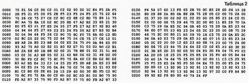
Codes firmware program of the microcontroller of the controller are given in table. 2.
Load current more than 2 obliterator should be installed on a heat sink. The heat sink plate case of obliterator is connected to the anode, so device devices can be mounted on one alloated. On site VD7 desirable to apply the Assembly of Schottky diodes (or two separate Schottky diode. for example. KDA). In a pinch you can use regular diodes, designed for the required load current. Good results can be obtained with diodes series CD. CD. CD. The LM393 comparator produces ON "Integral" under the designation IL393. You can use two separate comparator, for example, LM311. Instead transistor CPU be possible to apply bipolar transistor series KT815, CT, included in the collector circuit of the transistor VT2 resistor of 1 kOhm. To other details of the requirements are the same. as for the controller described above.
When creating a controller it connects the load and serves nominal mains voltage (for example, using Latri). Then, setting maximum power (100 %). A trimming resistor R21 achieve that the voltage difference at the inputs of the comparator A.2 was close to zero. After that reduce power to 90 % and include the "Automatic" mode. The adjustment of the resistor R21 achieve the coincidence of (±1) installed capacity and indications indicators in the status control mode of the controller (when the button is pressed "Automatic").
Literature
Author: L. Redico, Minsk, Belarus