


")

This controller differs from similar published the fact that it regulates (reduces) heat capacity of the soldering iron does not change its voltage supply and the interruption of the current through the heater at larger or smaller intervals.
Due to the large thermal inertia of the soldering iron it some time after the change of the average power reaches a new stable temperature of the sting. In addition, the device provides automatic shutdown of the soldering iron, if he is permanently on a stand. The controller is designed to work with a standard soldering iron. designed to operate from AC power.
Heater soldering iron is connected to the network through a contact a pair of electromagnetic relays. When permanently closed contacts soldering iron works in the rated power mode. If the relay coil to energize the DC pulse, the contacts are periodically opened and closed. Therefore, the average power generated in the heater soldering iron will be less than the nominal, and the smaller, the more time an open state of the relay contacts in relation to time closed. Control circuit depicted in Fig.1.
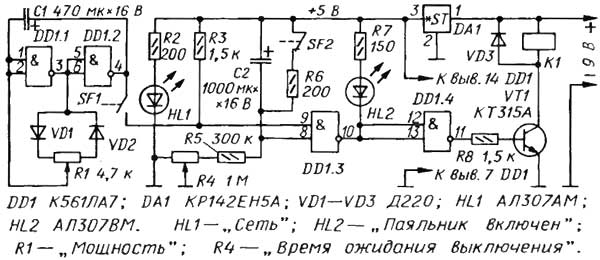
Fig. 1
Relay K1 serves as a load current amplifier transistor VT1 supplied from the voltage source V. 9 Element DD1.4 inverts the output signal of the element DD1.3. When the element DD1.3 is in the zero state, the led shines HL2 "Soldering on", open the transistor VT1, the relay K1 is enabled and the contacts (not shown) are closed - the soldering iron is warming up. On the element DD1.3, the capacitor C2 and resistors R4-R6 collected time relay. Contacts SF2 mounted on the soldering iron stand. When the soldering iron on the stand, contacts SF2 closed, the capacitor C2 is discharged, both the inputs of the element DD1 3 high level, and the output is low. Therefore a soldering iron is turned on.
If the soldering iron to put on the stand, his weight will open the contacts SF2 and will start charging the capacitor C2 through resistors R4, R5. After some time, depending on the circuit resistance R4R5, the voltage on the capacitor C2 will increase so that the element DD1.3 switches in one state. The led goes out HL2, closes the VT1 transistor will turn off the soldering iron. On the elements DD1.1, DD1.2 is assembled, the generator of rectangular pulses, the duty cycle of which may be changed by the variable resistor R1. Contacts SF1 switch combined with a variable resistor.
If you short circuit the terminals SF1, the voltage level of the lower circuit on the input of the element DD1.3 will periodically change from low to high and back with a frequency generator. The oscillator frequency {about 0.5 Hz) when you move the cursor of the variable resistor R1 remains almost constant. The duty cycle of the pulses (the ratio of the period of the pulse sequence to pulse duration) varies theoretically from unity to infinity. In practice, due to non-ideality of the diodes VD1, VD2, variable resistor R1 and logic elements DD1 chip, the extreme values of duty cycle a few don't make it to the unit or to infinity. In other words, in one extreme position of the slider of the resistor R1 soldering iron included almost constantly, and the other is off.
In intermediate positions of the engine, the relay is triggered by each pulse and the heater soldering iron receives a power pulse from the network. We note in passing that this method of control is called pulse width (SHI). The regulator is assembled on a printed circuit Board foil fiberglass with a thickness of 1 mm. the Drawing Board is presented in Fig. 2
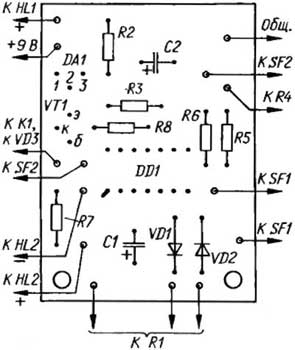
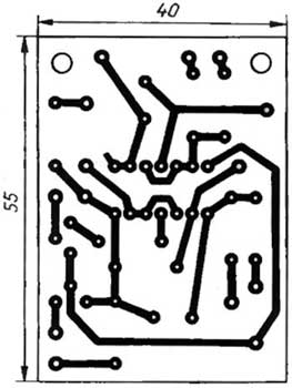
Fig. 2
It is designed to install the resistors MLT or sun. Oxide capacitors - K50-35. Stabilizer CREE can replace imported 7805 78L05 or miniature with its Pinout. Relay RES, execution RF4.523.023-01 or more, at a operating voltage of 9…12 V capable of operation when the voltage on the contacts 220 VAC. The variable resistors R1 - CP3-48M, R4 - CP3-46M. The fee is placed in the base of the stand soldering iron. Powering the controller can be integrated in a stand of low-power rectifier (on the scheme it is not shown) or from an external power supply. Switch SF2 is a contact group from any relay open type (the series RAN, RCN, RCM, ISU, etc.). The establishment of the regulator is not required. If you need to change the throttle limits the exposure time finding soldering iron on the stand to turn it off, have to pick up the resistor R5.
Author: A. Krynicki, Kazan; Publication: www.cxem.net