


")

This electronic component is designed to automatically control the rotation trays of eggs from the original position at an angle of 90 degrees with an interval of one hour.
One of the drawbacks of similar devices is described in "Radio" (see O. Glagoleva "Electronic automatic small incubator No. 3, 1997, p. 45, 46), - the difficulty of adjusting the switching node of limit switches, which will be triggered due to the inertia of the motor. In practice, to achieve this is very difficult, especially at low speeds, the Executive mechanism. Below the block is free from this drawback. Components and ease of fabrication is available even for not very qualified radio Amateurs.
The control unit (see scheme in Fig. 1) comprises a generator of pulses per second the elements DD1.1-DD1.3, the frequency divider circuits DD2-DD5 General the division ratio 3600, D-flip-flop (DD6.1), electronic circuit breaker (the transistor VT1), the actuator (relay K1, the motor M1, limit switches SF1 and SF2). The device is the preliminary chain the installation of meters in the zero state, as the moment of inclusion an actuator in the first cycle doesn't matter, all subsequent repeated every 60 min +15 C.
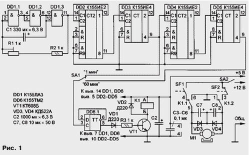
Second pulses from the output of the element DD1.3 enter the frequency divider. In depending on the position of the switch SA1 minute or hour pulses is input to the D-flip-flop (element DD6.1) and switch it on. Voltage high level arising on the direct output of the trigger opens the transistor VT1, which activates the relay K1 and holds it in this state until the next impulse. The relay contacts K1.1 through one of the limit switches, which in this point closed (on the scheme - SF2), connect the motor to the supply circuit. On the Executive mechanism of the limit switch SF2 last opens, disconnecting the supply circuit of the motor. Shutting in the beginning movement of the actuating mechanism of the limit switch SF1 prepares the circuit the motor power to a new cycle.
In the next cycle at the output of D-flip-flop - low voltage: transistor is closed, the relay is de-energized, the contacts K1.1 and K1.2 return to their original state and re-connect the motor to the supply circuit, but in opposite polarity relative to the previous cycle.
Mode "1 min" required to install trimmer R1 frequency generator to 1 Hz, and during operation - for installation in trays a horizontal position. Turns off the motor in this case produce switch SA2. Capacitors C7 and C8 suppress interference in the food chain operating engine.
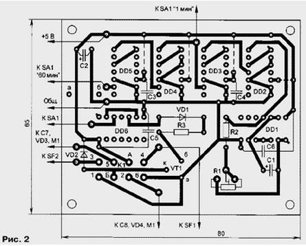
All the details of the block, except for the diodes VD3, VD4, capacitors C7, C8, end circuit breakers and switches SA1, SA2, are mounted on a printed circuit Board from foil fiberglass dimensions 65x80 mm (Fig. 2). On the Board has holes "a" and "b" for attachment of the capacitor C2.
In the relay device is applicable to RES-48 (passport RS4.590.204 or RS4.590.216), RES-9 (RS4.529.02903, RS4.529.029-10, RS4.529.029-12, RS4.529.029-15, RS4.529.029-16 or RS4.529.029-19) with an operating voltage of 5 V. it is Permissible to use relays operating voltage of 12 V. In this case, the power winding is carried out from same source as the motor power supply. Capacitors C1, C2 - C50-35, C7, C8 - C50-6, others - ceramic. The trimmer R1 - SP5-2. End switches SF1 and SF2 microswitches MP1-1. Switches SA1 and SA2 - tumblers MT. The motor - PDM-N-0.1 A.
Perhaps the use of AC electric motor for a voltage of 220 V with gear, for example, DSMU-P-220 50 Hz power 4∙A. in the device you should replace the relay on the triac and use both outputs of the trigger DD6.1 (Fig. 3). Kinematic diagram of the actuating mechanism for this variant is shown in Fig. 4. The drive plate And rigidly connected to the shaft of the motor and reducer rotates only in one direction. The rotation of the disc And 180 degrees corresponds to the rotation of the driven disk B at an angle of 90 degrees. Further rotation master drive causes rotation of the driven in the opposite direction.
These dimensions are determined experimentally. With any type of engine need, time to turn the actuator by 90 degrees (i.e. the time interval between the switching of the limit switches) did not exceed 1 min.
To power the unit, you can use any source dual voltage (stable 5 In and unstabilized 12 V. When replacing relays on the RES-9 partially need to modify the drawing of the PCB.
Author: A. Grigoriev, Balashov, Saratov region.