Recently in our everyday life is increasingly applied electronic devices for fine adjustment of the network voltage. With the help of such devices control the brightness lamps, the temperature of the electric heaters, speed motors.
The vast majority voltage regulators collected on thyristors, have significant disadvantages that limit their opportunities. First, they make a quite noticeable noise in electrical the network, which often adversely affects the operation of televisions, radios, tape recorders. Secondly, they can be used only to manage the load resistance of the light bulb or heating element, and cannot be used in conjunction with load inductive nature of the motor, transformer.
Meanwhile all these problems easy to solve, gathering electronic device, in which the role the regulating element should have been not the thyristor and power transistor.
Transistor voltage regulator contains a minimum of radioelements, does not introduce interference in the electrical network and supporting load both active and inductive resistance. It can be used to adjust the brightness the glow of the chandeliers or table lamps, the heating temperature of the soldering iron or the hotplate, the rotational speed of the fan motor or a drill, the voltage across the winding of the transformer.
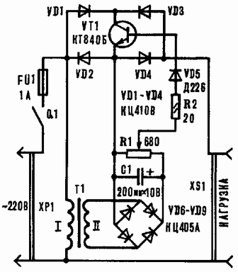
The unit has the following options: the adjusting range of voltage from 0 to 218 V; maximum power load when used in a control circuit of one transistor - not more than 100 watts. The regulatory element of the device transistor VT1 (Fig. 1).

Fig. 1
Diode unit VD1-VD4, depending on the phase network current and directs it to the collector or the emitter of VT1. The transformer T1 reduces the voltage of 220 V to 5-8 In which rectified by a diode block VD6 - VD9 and smoothed by a capacitor C1. Variable resistor R1 is used to adjust the amount of the control voltage, and the resistor R2 limits the base current of the transistor. Diode VD5 protects VT1 from contact with his base voltage of negative polarity. The device is connected to network plug HR. Socket XS1 is used to connect the load.
The regulator operates as follows. After turning on the power toggle switch Q1 mains voltage comes simultaneously, the diodes VD1, VD2 and the primary winding of the transformer T1. In this case the rectifier consisting of a diode block VD6 - VD9, capacitor C1 and variable resistor R1, forms control the voltage that is supplied to the base of transistor and opens it. If at the moment of inclusion in the network controller voltage was negative polarity, the load current flows through the circuit VD2 - the emitter-collector VT1-VD3. If the polarity of the mains voltage positive, current flows through the circuit VD1 - collector-emitter VT1-VD4. The value of the load current depends on the magnitude of the Manager the voltage on the base of VT1. Rotating engine R1 and changing the value a control voltage to control the magnitude of the collector current of VT1. This current, and hence the current flowing in the load, will be the more, the higher the level of the control voltage, and Vice versa. When the far right in the diagram the position of the slider of the variable resistor the transistor will be fully open and "dose" of electricity, consumed by the load will correspond to the nominal value. If the R1 engine to move to the left, VT1 will be locked and the current through the load does not flow.
Driving transistor, we actually adjust the amplitude AC voltage and current, current in the load. Transistor while running in continuous mode, whereby such the regulator is free from the disadvantages inherent thyristor devices.
We now turn to the design of the device. Diode blocks, capacitor, resistor R2 and diode VD6 are installed on the circuit Board the size of x mm made of foil Micarta or phenolic resin with a thickness of 1-2 mm (Fig. 2).

Fig. 2
All elements controller are accommodated in a plastic housing with dimensions HH mm. In the upper panel of the housing are mounted a toggle switch and variable resistor, is provided with a decorative handle. Socket the load connections and the fuse socket mounted on one of the side walls of the housing. On the same side of the hole made for power cord. At the bottom of the housing has a transistor, a transformer and circuit Board. The transistor needs to be qualified with radiator the scattering cross-section of at least 200 cm2 and a thickness of 3-5 mm.
The regulator does not need to establish. When proper installation and proper details it begins to work immediately after inclusion in the network.
Now a few recommendations to those who want to improve the device. The changes relate primarily to increase power output controller. For example, when using a transistor CT the power consumed by the load from the network, may be 150 watts, for KT - 200 W and for CT-250 watts. If you want even more to increase the power output of the device, as a control element you can apply multiple parallel connected transistors, and connects them to appropriate conclusions. Probably this case, the regulator will have to supply a small fan for more intensive air cooling of semiconductor devices. Except in the diode unit VD1-VD4 need to replace four more powerful diode, designed for a working voltage of 250 V and less the amount of current in accordance with load consumption. For this purpose suitable devices series D-D, D, D243, D - D. Need will also replace VD5 more powerful diode with a current capacity 1 A. Also, the more current has to withstand fuse.
Author: V. Ancev; Publication: www.cxem.net


