


")

Using relatively cheap a powerful field-effect transistors with insulated shutter (MIS transistors), it is possible to make a good device for regulation of the power of incandescent lamps, soldering irons and other equipment. The main thing unlike the proposed in this article construction from that previously described on pages the Radio magazine - low current consumption by control circuits, smoother regulation of power especially at the initial phase adjustment characteristics.
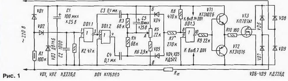
Schematic diagram of the device shown in Fig. 1.
(click to enlarge)
On the element DD1.1 collected the shaper rectangular pulses, in the form close to the "meander". Fronts and the busts of these pulses coincide with the moments of transition network voltage through zero. The pulses arrive at the differentiating circuit and C3R3 inverter DD1.2. After passing through the inverter, they are next on the chain C4R4. Diodes VD4, VD5 form element OR differentiated pulses through the divider R7R8 to the input (pin 8) of the element DD1.3, working as comparator. Capacitor C5 provides a smooth voltage regulation, it is especially important for filament lamps.
When you move the cursor of the resistor R5 (Fig. 2) changing the voltage at point a, and hence, the duty cycle at the output (pin 10) of the element DD1.3. And when the increase of this voltage, the duty cycle increases until the complete disappearance pulses and establishing at the exit of the element DD1.3-level log. 0 at the top diagram the position of the slider of the resistor R5, which corresponds to off load. When the decrease in voltage at point a, the duty cycle decreases until full merge, and settings on the exit of the element DD1.3-level log. 1. This happens the lower position of the slider of the resistor R5 and is fully enabled load.
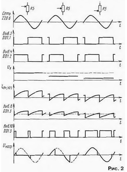
The input capacitance of a powerful field-effect transistors has significant value. For quick charge this capacitance, and hence fast switching transistor requires large currents. For this reason, the signal fed to the gate of the transistor VT3 through the current amplifier, transistors VT1, VT2. Transistor VT3 opens when the voltage is close to zero, and is closed when the voltage determined by the position of the slider of the resistor R5.
In the power control used fixed resistors MLT-D, AC SP-1; oxide capacitors - K50-35, the rest - km-6. Diodes CDD (VD1, VD2 and VD6-VD9) can be replaced with any reverse voltage of at least 400 V and maximum continuous direct current of at least 1 A. the Zener DB(\/D3) replace other with 9V voltage stabilization. Replacement chip KDE (DD1) others, such as the series C, unwanted. The fact is that when the voltage on the entrance than levels 0 and 1, in the mos IC arise through currents [1] and, as shown by measurements, even in the static mode for input voltage, close to threshold, they can consume current from the hundreds of microamperes (for chips series C) and up to tens of milliamps (for chip series C). If you increase supply voltage current consumption increases dramatically. It was also found that, if on one of the input circuits voltage corresponds to a threshold, and others 0 or 1, the current consumption is about 20% less, if at all the inputs were present threshold voltage. With this in mind unused inputs should be connected to GND.
Chips instead of CLI you can use MLA, but its inputs (pins 2,5,9) via 10 kOhm resistors to be connected to the output 14. Transistors CTB, CTSB (VT1, VT2) interchangeable with any low-power, appropriate structure. Powerful field-effect transistor with insulated gate and the n-type channel KPA you can substitute used in TV power supplies CPU [2, 3]. Good results are obtained with transistors BUZ90, as their input capacitance almost an order of magnitude lower than that CPU.
Controller design can be any. It is only necessary that the length connecting wires was minimal. VT3 transistor mounted on dural teplota-de area of 24 cm2. Available inputs of the element DD1.4 (findings 12 and 13) is connected to the output 14 DD1.
To configure the controller will need an oscilloscope with an input impedance of not less than 1 mW. Begin with switching on the device without load. When you move engine resistor R5 to the output 10 of the element DD1.3, there should be a change pulse ratio. Then check the voltage at the Zener diode VD3 all the provisions of the R5 engine and if it drops below 7 To reduce the resistance resistor R1. Further, instead of the load connect a resistor-1 resistance 100…300 ohms and clarify the limits of the power control. For this engine resistor R5 is set in upper circuit position and the selection of resistor R7 find its minimum value at which the output 10 of the element DD1.3 absent pulses, and the voltage will correspond to the level of the log. 0. Then the engine of the resistor R5 is moved to the lower position and pick up the most possible resistance of the resistor R6. wherein at pin 10 of the element DD1.3 the voltage will correspond to the level of the log. 1.
After that check the operation of the device in different positions of the engine of the resistor R5, controlling the waveform at the load. In the case of self-excitation of the device it eliminate the selection of the capacitance of the capacitor C2. It should be noted that in extreme provisions engine resistor R5 slight asymmetry of the voltage on load. This can be reduced by selection of capacitors C3, C4 and resistors R3, R4.
If you want to connect more powerful the load, the diodes VD6 - VD9 replace more powerful and increase the area of the heat sink of the transistor VT3. Possible option parallel connection of several field-effect transistors.
On the basis of the regulator it is possible to make the device a smooth on-off switch incandescent lamps. To do this, remove the resistor R5. R6, between the points a and B the two sets of series-connected resistors the resistance 47 kOhm. Between the connection point of these resistors and the point In install the switch. The capacitor C5 is replaced by another with a capacity of 47 µf and the operating voltage of 25 V. the current Amplifier (VT1,VT2, and R10) are permitted to exclude, and the resistance of the resistor R9 to reduce to 12 ohms.
The device is conveniently mounted within the junction box. In parallel the switch can be set by the Executive chain of the optocoupler, the led part which provide signals from an external programming device, for example, described in [4]. It. in the absence of the owners of the apartments will include a light for a while in the dark, thereby discouraging uninvited "guests".
When you configure the controller, you must exercise special care because the device has no galvanic isolation from the mains.
Literature
Author: S. Zorin, city of Znamensk of the Astrakhan region.