The author argues that the proposed electronic device can to be successfully used to regulate the operating temperature of the sting the soldering iron, stoves, furnaces, and other similar loads with large thermal inertia.
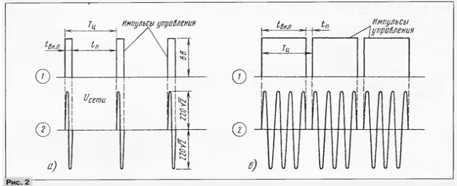
From similar power regulators described earlier in "Radio", the proposed the device is simple to control triacs, switching load operating in intermittent mode. This mode is characterized by the fact that the duration of the regulatory cycle is constant, and the length of the inclusion load changes and pauses, or changes the duty cycle - the ratio on-time load for the duration of the regulatory cycle. In the embodiment the regulator in question, the cycle time is chosen to be 45, and the range of modulating power to the load is 5% to 95%. Maximum the load power is 2 kW.
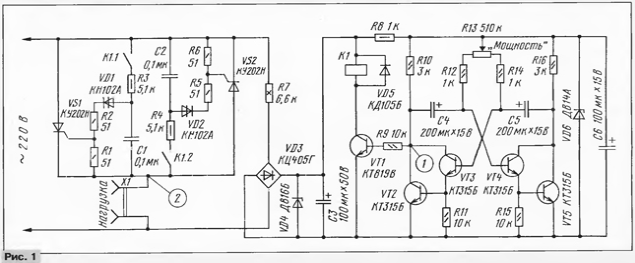
Power control (Fig. 1) consists of the symmetric multivibrator to transistor VT2 - VT5, the current amplifier multivibrator transistor VT1, electromagnetic relays K1 and triacs VS1 and VS2, performing the function electronic switches. Resistor R13 change the duty cycle management at the collector of transistor VT2, and hence the power in the load connected to the connector X1. In this case, the period of pulse repetition the multivibrator is changed slightly. Resistors R12 and R14 limits the current in the base circuits of transistors VT3, VT4 when the final positions of the engine, variable resistor R13.

Diode bridge VD3, resistor R7, absorbing excess voltage, capacitor C3, smoothing the rectified voltage ripple, - transformerless unit power the device. Zener diode VD4 limits the output voltage rectifier, up to 25...28 V when the transistor VT1 is closed and the relay K1 is in its the collector circuit is de-energized.
Switching the load being carried by the contacts K1.1 and K1.2 relay K1 in chains start triacs VS1, VS2. The start node of the SCR VS1 form the contacts K1.1 relay, resistor R3, capacitor C1, dinistor VD1 and resistors R2, R1, and the node startup of SCR VS2 - contacts K1.2, resistor R4, capacitor C2, dinistor VD2 and resistors R5, R6.
When the relay coil is de-energized and the contacts K1.1 and K1.2 open, both SCR are in the closed state and the power in the load is zero. When the control pulse opens the transistor VT1, the relay K1 is activated and closed contacts K1.1 and K1.2 includes a circuit run of triacs. With this the moment of SCR VS1 begins to pass positive half network voltage, and VS2 - negative.
SCR VS1 offer current pulse discharge of the capacitor C1 is supplied at its control electrode through a dinistor VD1. Charging the capacitor C1 AC line voltage through a resistor R3 to the moment of switching dynistor. Resistor R2 - tocook-rangiwai. The resistor R1 is required for secure closure the SCR VS1. While SCR is open, the voltage drop on it has no no influence on the chain running to the end of the half cycle of the mains voltage.
The same is true for SCR VS2, but with a negative half-wave of the network voltage. And since switching voltage dynistor VD1 is about 20 In the switching of the load occurs at the same voltage low level interference, no appreciable effect on the operation of other electrical appliances, powered by the same AC. When closing the transistor VT1 the relay coil K1 is de-energized, the contacts K1.1 and K1.2 open and load disconnects from the network.
With admission to the base of VT1 next control pulse of the multivibrator cycle regulation of the power in the load is repeated.
The principle of operation of the regulator illustrate the timing diagrams shown in Fig. 2. It diagrams and correspond to the minimum power mode, and chart b - max.

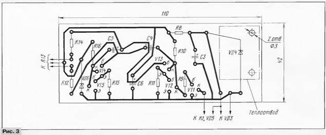
The details of the control unit are mounted on the PCB size 110x42 mm (Fig. 3), made of one-sided foil fiberglass. The rest on the breadboard (the PCB has not been developed), the size of which was dictated by the dimensions chosen details. Oxide capacitors - C50-6. The resistor R7 is composed of three series-connected resistors sew-10 or Sew-7,5 resistance 2.2 kω each. It will replace a capacitor of 0.47 UF rated voltage not less than 400 V. in Parallel with this capacitor you should connect the resistor 510 Ohm 0.5 W in series with capacitor - 36 Ohm of the same capacity. Variable resistor R13 - SP-1 group But, the rest of the IFL.

VT5 - any silicon structure n-p-n with a static coefficient of transmission the base current of at least 30. Transistor VT1 can be KT815 or CT alpha index B - G Instead of triacs CAN (VS1, VS2) suitable COM, KUK, COOL. Relay K1 - RAS at a voltage of 24 V.
Structurally, the regulator is made in the body from the monthly speaker. Variable resistor R13 is in place of the volume control. If it groups But, the scale of power control is obtained by a linear. Triacs VS1, VS2 and Zener diode VD4 mounted on finned heat sinks.
Accurately assembled the regulator does not require networking. To check it the health connector X1 need to connect the incandescent lamps 100...200 watts. Change the duration of the glow lamp and the pause between her inclusions during rotation of the handle of the resistor R13 "Power" indicates work properly device.
Load controller described here for over two years serves as an electric stove, which failed bimetal temperature controller heating. Average daily duration of work 3 4 hours...At the time of operation was not one failure, completely eliminated the problems with bimetal contacts thermostat.
Author: Y. Nigmatulin, novopetropavlovskoye Kurgan region.


