


")

This article describes a digital multi-meter based on PIC controller that can perform the functions of a multi-program timer, able to manage four loads, clock, alarm clock, broadband and thermometer the thermostat that provides both heating and cooling controlled object.
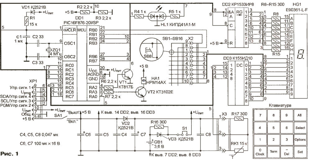
Universal digital device, scheme of which is shown in Fig. 1, has the following technical characteristics:
- simultaneous or separate run to nine software timers;
- clock function and alarm;
- the light and sound signals when triggered by any of the timers or alarm;
- the possibility of issuing up to four signals that control external devices;
- the function of the thermometer (measured temperature - from -43 to +470 °C, the average error - no more than ±2 °C);
- function controller (supported temperature - from -43 to +470 °C) with selectable operation mode (heating or cooling).
(click to enlarge)
Control the device using a 16-button keypad. Provides for the inclusion and off podzvuchivaniia pressing buttons, setting up sound, lighting and control signals, the possibility of individual settings of the device under a specific application by changing the control program MK. There backup power built-in rechargeable battery. All installed when the product settings are saved even if you turn off backup power in for more than 40 years.
As can be seen from the diagram, the basis of the device - PIC-controller DD1. The shift register and DD2 the decoder is designed for DD3 organization dynamic display, the principle which is as follows. Initially, the decoder DD3 served code 1111, therefore on all its outputs are set log levels. 1 and none of indicator bits HG1 not lit. Next to the register DD2 code is logged required symbol, then DD3 served code corresponding to the desired the category indicator.
Simultaneously with the update data for the indicator scans keypad, 16 buttons which are divided into two groups with eight in each. General conclusions buttons these groups are connected to two inputs of the MC (RB0 and RB1). When pressing any button on one of these inputs the signal log. 0 the corresponding output of the decoder DD3, thereby defining its code.
Using the keyboard you can start/stop any of software timers or all at the same time, to set the operating mode of the thermostat, the current time, the alarm time, etc. Most buttons have a dual purpose depending from what information a user enters on the keypad: numeric or administering.
Consider the functions of the buttons of the keyboard in more detail.
"Oh", "Clock" - a " 0 " when entering numeric information or switch hours in which to change the current time, set time enable alarm, switch alarm of the new hours to edit correction factor (see below).
"1" - "9" - the numbers 1 - 9 when entering numeric information, or select the corresponding program timer.
"Term" - the mode of the thermostat where you can set the current value temperature, to edit the value of the controlled temperature type regulation (heating or cooling) and the parameters of the thermistor.
"Del" - the minus sign when entering controlled temperature the on/off thermostat, thermometer, alarm or hours (at off instead of the appropriate indications are displayed marks ---), reset when entering numeric data.
Set the transition/output mode change the value of any parameter (program timer, current time, alarm, thermometer, the controller settings).
"Options" - go to change mode settings. Here you can enable/disable podzvuchivaniia buttons, welcome select sources governing the issuance signals, etc.
Select - start/stop the current program timer, if set exposure time is different from 0.
"An" - start/stop all software timers, the value of time delay which is different from 0.
The unit can generate four control signals, each of which can be used at the discretion of the user. Have the opportunity to ask the source the issuance of these signals:
- the signal will be active (to have the level of the log. 1) when one of the timers the number of which is specified by the user;
- the same, when any number of timers and inactive after exposure all timers;
- signal will be activated upon actuation of the thermostat.
The device uses two-color led HL1, which blinks red color, if you start one or more timers at least one control the signal became active, and green when active signals no.
At the end of the exposure time of any running timer indicator HG1 begins to flash and the piezo oscillator HA1 with a built-in breaker delivers the the sound signals. This continues until the user presses any button on the keyboard or not pass a certain time, the value of which is stored in the memory MK and can vary when programming. Sound signal is issued when the timer defined by the two parameters: the duration and number of audio packs.
When the alarm also sounds, but start to blink only two of leftmost character of the indicator - A and L (from the English. ALARM - the alarm clock). The alarm is also described by two parameters, stored in the memory MC.
Depending on the applied quartz resonator clock accuracy it turns out different, so this device is implemented in software time correction. The correction coefficient set by the user from the keyboard and also stored in the memory MC. Actually it is a number of microseconds, which is added to the periods of the oscillations generated by the internal timer MK - in our case of 1.92 MS. Using the correction factor are making to it time has become equal to 2 MS (time period 1 is logged after every 500 such periods).
The temperature is measured by measuring the voltage drop across the PTC resistor RK1. Its resistance depending on temperature is determined by the following formula:

where R0 is a constant that has the dimension of resistance; C - constant with the dimension of the temperature; T is the absolute temperature. Thus, this dependence should lead to linear. The known method of linearization using electrofusion of the bridge, but this approach is inconvenient that when replacing thermistor have to change settings and the bridge that is not so easy.
More convenient it is to obtain the temperature value without any linearization, but you need to calculate the value of the following expression:
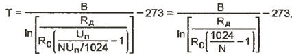
where Rd is the resistance of the additional resistor; N - 10-bit binary code, obtained after analog-digital conversion; Un - supply voltage.
In the described device the expression is evaluated by the control program MK, and the result appears on the display. It should be noted that the above interval measured and controlled temperature (-43 to +470 °C) can be arbitrarily stretch, squeeze, or move. This interval was chosen because it the temperature measurement error does not exceed ±2 °C. the resistance additional resistor R17 is equal to 300 Ohms. To reduce it by error to increase, however this will change the boundaries of the temperature range. For easy calculations you can use the term paper (10 bit).mcd for the system MathCAD 2001, which for the given parameters of the thermistor RK1, resistor R17 and required error calculates the interval of measured temperatures.
To when main power off clock real time lost, the device has a node backup power MK. It consists of battery GB1 voltage of 3.6 V, a resistor R16 and diode VD2, VD3. When you turn on the main power diode VD3 is closed, and the battery GB1 is charged via the resistor R16. If the mains supply voltage the battery is supplied through the diode VD3 only on MK (supply voltage at the remaining elements of the device prevents the diode VD2). The MC determines the fact power, as it continuously monitors the voltage level at pin RB2. And when it becomes equal to the log. 0, MK ceases to carry out the regeneration display and keyboard scanning, stops all running software timers, stops to measure and adjust the temperature and switches to the clock mode. Except if while working with the instrument settings were changed, after power outage briefly flashes the red led, if the settings are not changed green. If the device is assumed not to use for a long time (a week or more), it is possible to exclude a full discharge battery you can turn off backup power by jumper S1.
MK constantly monitors the status of the push-buttons on the keyboard, and if for a given time was not a pressing one, and has not been started nor one program the timer, it automatically switches to the clock mode.
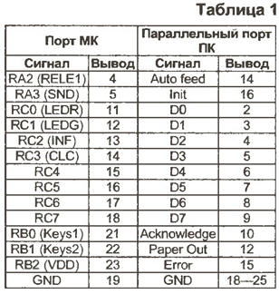
The control program MK written in C language so it can easily to use any data types, including real. Program were developed in the programming system HT-PIC (it can be downloaded from the website <www.htsoft.com>). For debugging used simple in-circuit emulator, which is a set of contacts connecting the parallel lines port of the computer to the wall outlet under the microcontroller on the main Board. Compliance findings the parallel port of the computer socket outlet MK on-Board timer is shown in table. 1. To control the emulator control program MK was compiled with small changes in the programming environment Borland C++ 3.1.
Unfortunately, the work of such emulator occurs in the time scale, excellent from real, but nevertheless, without such a device it would be practically impossible to debug such a complex program. Without the use of emulator was sold only analog to digital conversion, the description of which for purposes of this MC can be found on the website <www.microchip.ru> (document DS30292C - "Module 10-bit ADC in the PIC16F87x microcontrollers").
Briefly review the highlights of the work control program MK. It is written using the methodology of structured programming, resulting has a large number of subroutines. After power-up the MC configures ports I/o, ADC, and internal timer. Then starts executing the main loop, which is infinite. In it, as already mentioned, is constantly checked the presence of a base supply voltage, and in case it is disconnected MK stops to perform all functions, except timing. When you turn on main power he displays the splash screen and goes back to operation mode.
The information that must be displayed on the indicator currently in use, is stored in the array d. During regeneration of the indicator MK rewrites its contents in an intermediate array, and from it sequentially reads the codes displayed characters and displays them on the display. An additional array is introduced for the purpose to eliminate the flickering of the indicator resulting from the entries in the array d new information before old is not yet fully mapped. For example suppose that initially, the array d contains the string "ABCDEFHLP" and displaying fourth character ("D") in the array included the line "FDA 2002". Then the user of the device due to the inertia of the human eye at some point of time will see the string "ABC 2002". In addition, if similar processes are repeated constantly (as they will when the real work), the person will develop the impression that the information on the indicator flickers.
As noted, simultaneously with the update of the indicator scans keyboard. When any button is pressed, the routine is called suppression bounce contacts, which effects a delay of a few milliseconds (the value of this time is stored in the memory MC), during which the device is on further pressing the buttons does not respond.
It should also be noted that the development time of software timers, watches, and the alarm is set in seconds (hours counter is reset when it reaches 24 x 60 x 60 = 86400), and prior to output of the indicator is converted to the format H : MM : SS for timers or in the format HH : MM for hours and alarm. Runs this is using the following formulas:
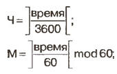
C = time mod 60.
Here operation ][ means discarding the fractional part, i.e., the division is integer.
The obtained values of hours, minutes and seconds until it is not fit for the direct output of the indicator, as represented in binary code. To select senior and Junior decimals is required on each set to perform two operations:

LSB = value mod 10.
Let us consider an example. May be displayed on the indicator value 8673 with in the format H : MM : SS. Get
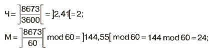
C = 8673 mod 60 = 33.
Thus, the indicator will change to 2 : 24 : 33
From the above examples shows how many surgeries should only be done for the output of the indicator. To realize such in the language of mathematics assembler would be almost impossible. In the language of the same si this is implemented a few lines, in this case, due to the high level of optimization the code is quite compact and fast. But most importantly - the programmer may focus most of our attention on the algorithm program, abstracting from the specific features of the architecture used MK. All this contributes to the easy transfer program from one MC to another.
The source code of the MC codes and firmware in Intel HEX format are the above Internet address.
For programming the MC, the author used the programmer, assembled according to the scheme depicted in Fig. 2, and PonyProg2000 software, latest version which can be downloaded from the website <www.lancos.com>. The main difference the programmer described in [1] is to add another transistor (VT3) in the chain of formation of the synchronization signal, which increases the reliability of programming due to the complete elimination of the negative voltage on the findings of the MK.
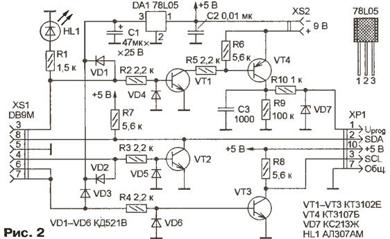
The described device allows the programming of the MCU on the Board, i.e. supports ICSP (In-Circuit Serial Programming in - circuit sequential programming). To do this, connect the five wires of the programmer via connector X1 as follows: 7 - total; 5,6 - 5; 2 - SDA; 3 - SCL; 1 - Uprog.
Use other programmers, including support low-voltage programming. In the latter case, you need to connect corresponding pin of the programmer with the contact 4 of connector X1.
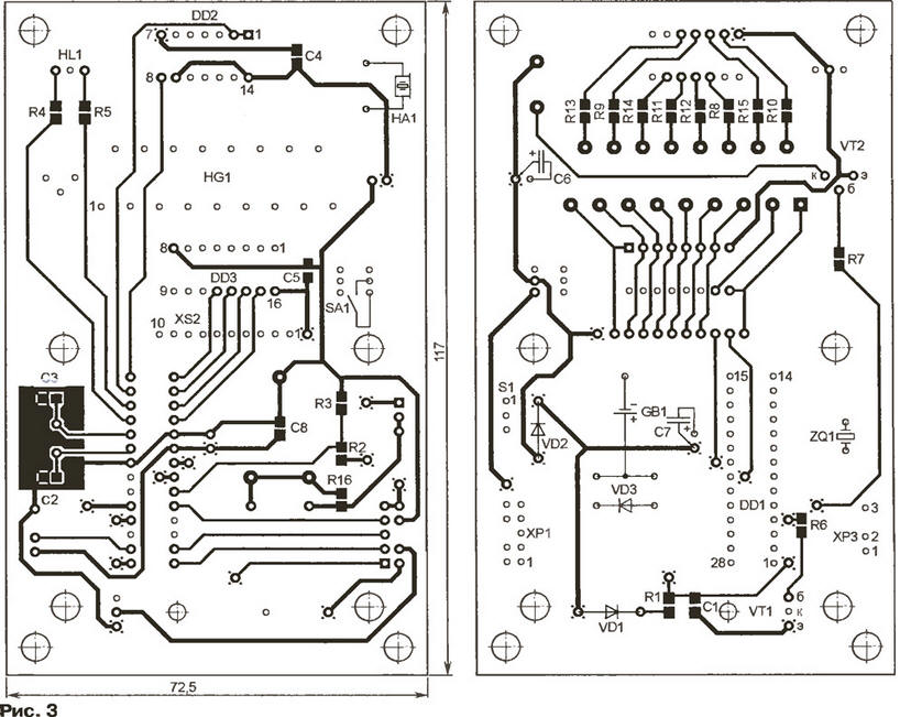
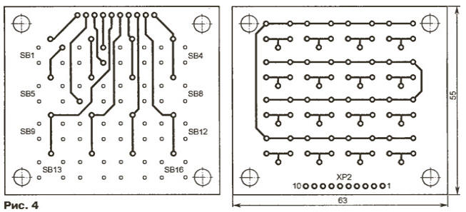
Drawing of the PCB of the device depicted in Fig. 3, the keyboard in Fig. 4.
(click to enlarge)
On circuit Board timer has seven holes in which to insert installation details pieces of tinned wire and solder them to the printed conductors on both sides Board. The function of the jumpers perform and the conclusions of some of the parts. Holes through which are similar compounds printed conductors allocated to Fig. 3 four cross-shaped dots.
The project source files and a library of components used for CAD Accel EDA 15.0 located at the above website.
The device is equipped with fixed resistors and capacitors, surface installation. Exception - oxide capacitors C6, C7 (K50-35). MK part no pic16f876 can to have any maximum operating frequency and temperature range, most importantly, so he was in a DIP package (suffix SP). The system can NRMF to replace a node that is executed on three elements of the chip and CRUZ the piezo oscillator SN-18 [2]. The thermistor RK1 - MMT - 4 with a nominal resistance 15 ohms (R0 = 0,294 Ω, = 3176).
As connectors X1 - XS applied split pads with straight pins used in computing: for X1 is used block double row arrangement of the pins, for x2 and XS - with-row. Eighth contact fork HR and third plug XP2 removed, and in their slots, return of parts connectors plugs inserted - cuts thick fishing lines. This measure is not will incorrectly dock connectors. Socket connector made of x2 20-locular panel under the chip in the DIP (used one part of it, having 10 contacts). Button SB1-SB16 - TS-A3PS-130.
The contents of the EEPROM MK, which you can modify to specify other parameters the work presented in tab. 2.
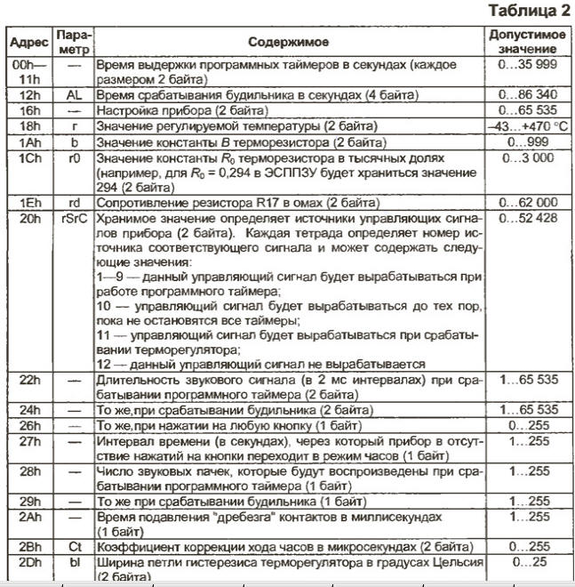
(click to enlarge)
In the column "Parameter" is the name of the parameter, which is displayed on the indicator. If this column is blank, then this parameter can only be changed when programming the MC.
Literature
Author: D. Frolov, Ryazan