


")

In the home and at work quite often the need to maintain a constant temperature in the room in the vessel with the liquid, etc. there are many electronic devices for automatic maintain the temperature. Some of them are difficult to manufacture and contain deficient elements, others do not have galvanic isolation with the mains supply and therefore unsafe operation.
The proposed variant of the thermostat provides maintaining an accuracy of ±0.5°C temperature set from 10 to 50 °C. the Power of the heater is connected to the thermostat, should not exceed 2 kW. The main advantage of the device - easy in the manufacture and availability of components.
Schematic diagram of the thermostat depicted in Fig. 1. The device is a set of four functional units: a Schmitt trigger, multivibrator transformer and trinistorny key.
Schmitt trigger monitors the resistance of the thermistor RK1 - temperature sensor. When the resistance of the thermistor, while decreasing passes the lower threshold, the Schmitt trigger switches and its output signal inhibits the multivibrator. As a result, trinistorny the key does not pass current through the heater. With increasing resistance thermistor above a certain upper threshold of the Schmitt trigger switches back to its original position and allows the multivibrator, pulses which open the trinistorny key. As a result through the heater electric current. This process is repeated with a frequency that depends on the power of the heater, the difference between the values of the set temperature of the object and the temperature of the environment, the thermal inertia of the object and the width of the hysteresis loop of the trigger Schmitt.
The Schmitt trigger is built on transistors VT1, VT2. In the emitter circuit of these transistors includes two diode VD4, VD5. For the expense of nonlinearity was able to narrow hysteresis loop trigger and increase the accuracy of temperature. Resistor R2 sets the limits regulation of temperature, and resistor R1 is the specific value of temperature in these limits. The connection between the transistors VT2 and VT4 direct, therefore, if the first one is open, the second closed, and Vice versa.
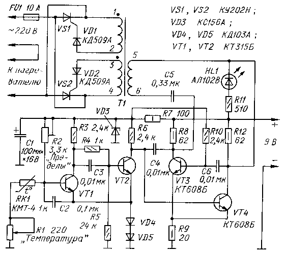
Fig. 1
The oscillation frequency (about 20 kHz) of the multivibrator, collected on transistors VT3, VT4, determine the resistor values R6, R10, capacitors C4, C6. The frequency is selected on the basis of conditions reliable opening of the SCR, which requires momentum on the control electrode of at least 10 μs.
The multivibrator is inhibited, when the transistor is open VT2.
Pulse transformer T1 provides galvanic interchange switched circuit, and a control device that complies electrical safety requirements in the operation of the thermostat. Primary winding of the transformer is connected to the collector of transistors VT3, VT4 through the coupling capacitor C5, which eliminates the connection between them and the transformer DC. This way of eating the primary winding of the transformer provides a current flow in two directions, which increases the efficiency of transformation.
Winding 1-2, 3-4 transformer connected to the Manager transitions through the triacs diodes VD1, VD2. This ensures alignment the load in each half-wave control pulse and negative cuts the voltage on the control electrodes of the triacs. Parallel the inclusion of triacs allows you to skip both positive and negative of the half-wave of the mains voltage through the heater without the use of rectifier the bridge, which stands out useless considerable power.
HL1 led indicates the heater is turned.
In the device used resistors JS1 (R1, R2), OMLT (R7, R8, R9, R12) and MLT (the rest). Capacitors km (C2-C6) and K52-1 (C1). Transistors VT1, VT2-KT315, and VT3, VT4 - CT, CT with any letter. Is indicated in the diagram, the diodes can be used KDA (VD4, VD5) and CDA (VD1, VD2).
If the power of the heater exceeds 200 watts, triacs must be installed on the heat sinks. When the power not exceeding 300 W, instead CAN you can use triacs KUN.
Transformer T1 is wound on the ring size HH mm, ferrite 2000NM. All three windings are identical and contain 50 turns of wire PELSHO 0,17. In the manufacture of the transformer need take steps to ensure that it is capable of withstanding the voltage between the windings at least 600 V.
The current consumed by the regulator, does not exceed 250 mA at a voltage of 8…12 V
Before turning on the controller in the network must to install the resistor R2 to the middle position. If this resistor will be decided to be located on the front panel, it must consistently to include a limiting resistor 300.. .510 Ohms.
Correctly assembled the thermostat starts to work immediately. Only in some cases requires the selection of the resistor R3.
Author: Y. Mayak, Kharkov; Publication: www.cxem.net