


")

The device is universal and is designed to maintain a fixed value predetermined positive temperature range +1…80 °C with an accuracy of 0.2 °C.
The thermal stabilizer may be used in artificial the incubator for the hatching Chicks from eggs (+37,5 °C), drying oven (+60 °C), homemade bath, or to maintain a positive temperature (+2 °C) in heated storage room for vegetables on the balcony with a negative temperature air. In this case, the operation of the device is not affected by possible instability the mains voltage.
Powered transformerless device according to the scheme (Fig. 1.15) directly from the network 220, which can significantly reduce it's dimensions.
The principle of operation of the circuit in the comparator D1 in particular the explanation is not alien - he is often used in various devices and described in the literature. A feature of this inclusion of the comparator is management load output at the emitter output of the chip. The use of the transistor VT1 can enhance the functionality of the comparator and to simplify the control circuit of the thyristor.
As the heater will suit any load capacity no more than 1000 watts (I used "air" heater 500 watts - it is more durable than the heater of the bulbs). If you want to manage more powerful the load, the diodes VD3…VD7 must be applied to more valid operating current (for example DA, B, DA, B) and connect the additional thyristor together with another transistor KTA similarly with the above scheme. Signal control the second load (it connects to individual nests) removed with output D1/1.
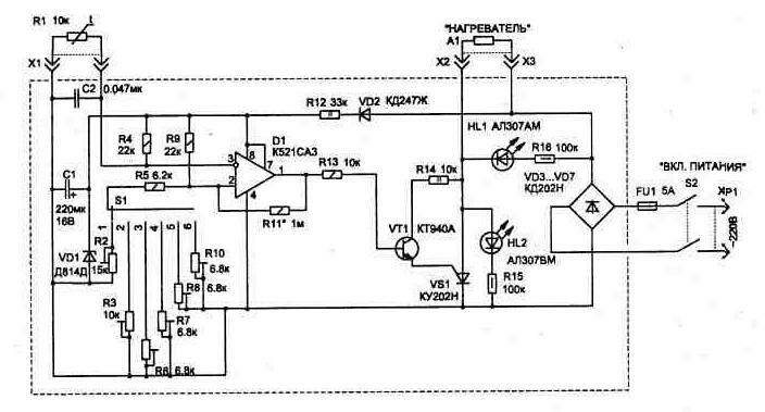
Fig. 1.15
To control the load capacity of 1000 watts you can apply one thyristor type T-20-4 or T-25-4 (the last digit the designation may be more).
The mode indicator schemes are LEDs HL1, HL2. Thus, the device is switched on by the switch S2, if heating is not connected element A1 (or is blown), the glow will be simultaneously both LEDs, and during normal operation of the illumination device between the indicators will be followed: during heating A1 glows red led HL1 (the thyristor is open), during the cooling HL2 - green.
In the scheme used as a temperature sensor thermistor type STZ-19 (he has small dimensions and mass), but and other types (this may increase the thermal inertia).
For easy operation heat stabilizer is used switch (S1), which lets you have 5 fixed values of temperature and one variable. In the sixth position of the switch variable resistor R2 allows to set any temperature within the specified range.
The most commonly used temperature convenient to adjust the resistors R3, R6…R8, R10 (multi-turn actuator, type SP5-2) in the respective positions of the switch.
The circuit has fixed resistors C2-23; variable resistor R2 type JS2-2; capacitor C1 is K50-15, C2 - K10-7V; switch S1 type PG-5-PN; the switch S2 type TK; connector X1 - RS-4; socket x2, XS type G4,0 .
In the manufacture of construction necessary to provide heatsink for thyristor VSI and diodes VD3…VD7.
The appearance of the casing structure shown in Fig. 1.16. Is he from dielectric materials.
The connection cable from the socket X1 to the temperature sensor can be up to two meters and is intertwined between a wire - this will reduce the effect of noise and interference at the input of the circuit.
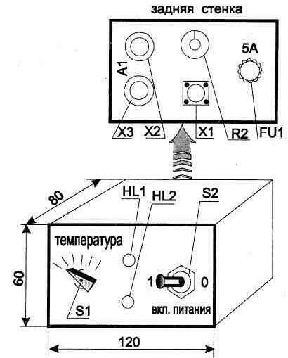
Fig. 1.16
Publication: www.cxem.net