Spring and autumn (and sometimes, and in summer in garden small houses have to use electric heaters. The savings in this case cottagers electricity will help they offer a thermal stabilizer that will support night the room lowered temperature, and in the morning bring it to a "comfortable" values.
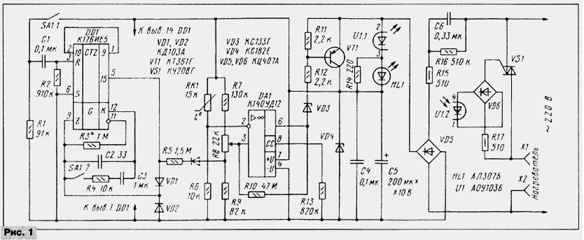
The heat stabilizer (see scheme in Fig. 1) contains electrofusion bridge RK1, R6-R9, a comparator operational amplifier DA1 and the control circuit of the triac VS1, made somewhat unusual.

In the heat stabilizer is applied to the power supply unit with damping capacitor C6. In the output diagonal of the rectifier bridge VD5 connected in series United emitting diode U1.1 of the optocoupler U1, led HL1, indicating the heater is turned on, and a Zener diode VD4, the voltage from which is applied to power other components. When closed, the transistor VT1 through emitting diode of the optocoupler flowing pulsating current with an amplitude of about 32 mA. The ripple voltage on the Zener diode VD4 smoothed by capacitor C5. His the maximum value of the current through the emitting diode reaches in moments of transition mains voltage through zero, i.e., exactly when you need to include optocoupler U1 and triac VS1. Average current at the output of the bridge is about 22 mA, which is more than enough to power the rest of the items heat stabilizer.
When the temperature of the thermistor RK1 is lower than the set voltage the noninverting input of op-amp DA1 higher than the inverting, the voltage at the output of op-amp close to the voltage at the plus output of the capacitor C5. The Zener diode VD3 and transistor VT1 is closed. Through the optocouplers emitting diode flows the current of the diode bridge VD5, the optocoupler turns on and includes a triac VS1. On the heater comes voltage, led HL1 in its illumination indicates this. First the inclusion of the triac VS1 will happen at an arbitrary time, after which he will be included at the beginning of each half period, which will provide a low level interference.
When the temperature of the thermistor increases to installed, the OS will switch and the voltage at the output will be close to the voltage of the negative output capacitor C5. Opens the Zener diode VD3 and the transistor VT1. All current diode bridge VD5 will go through the transistor VT1 past emitting diode of the optocoupler U1 and LEDs HL1, with the majority still will flow in the Zener diode VD4, and smaller through the resistor R12 and the Zener diode VD3 at the output of op-amp DA1. Optocoupler U1 and triac VS1 will no longer be included at the beginning of each half cycle, the heater will be disconnected from the network.
Temperature balancing electrofusion bridge RK1, R6-R9, which supports thermal stabilizer, depends on the voltage at the output 15 of the chip DD1. At a high level on this output voltage at the AC engine resistor R8 is somewhat larger than at low. The balance of the bridge corresponds to lower resistance of the thermistor RK1 (higher temperature).
At the moment the heat stabilizer in the network when you open contacts switch SA1 starts the pulse generator on the elements of the chip DD1 findings 9, 11, 12, the resistor R3 and the capacitor C2 [1]. Frequency generation is about 20 kHz and, regardless of the initial condition triggers, not more than 16384 period generator (less than 1) at the output 15 of the chip DD1 will high logic level. Through the diode VD1 he will arrive at the input Z generator and will not allow his work [2].This mode is essential for heat stabilizer.
If you now close the contacts of switch SA1, the input R of the chip DD1 you will receive an impetus and install the latest trigger counter DD1 chip to zero condition (all previous triggers to this point are already in it). On the output 15 will appear low logic level. The pulse duration is selected equal to 60 MS, which guarantees the beginning of operation of the counter after the end of the contact bounce of the switch. The connection of the capacitor C3 in parallel C2 leads to the decrease of the oscillation frequency in 30 000 times and finding period the pulses at the input of the counter chip DD1 about 1.5 C.
The presence of a low logic level at the output 15 DD1 reduces the voltage on the engine of the resistor R8 and the stabilization of lower temperature than in the main mode.
After about 7 h after closing the contacts of switch SA1 output DD1 15 appears high logic level, the generator will be stopped and again the thermal stabilizer go into basic mode.
To restart the stabilization of low temperature it is necessary to unlock and again close the contacts SA1. In the basic mode of operation of the contacts SA1 better to keep open. In this case, after interruption of the mains voltage the stabilizer immediately goes into basic mode.
The resistor R4 and the diode VD2 suppress interference pulses of negative polarity at log Z DD1 chip generated during the recharging of the capacitor C3. When the absence of these elements these pulses through the diode VD1 are part of the output 15 chips and electrofusion bridge, disrupting the normal operation of the shelter DA1. Own protective diode DD1 chip, VD2 are connected in parallel, has too much resistance.
Resistor R10 provides a small hysteresis Oh DA1, which also helps his precise work. Resistor R13 sets the operating mode of the OS, and R14 reduces the current through the led HL1 to valid values.
Electrofusion bridge was calculated according to the recommendations outlined in the paper [3]. In the device used a thermistor MMT-4 resistance 15 ohms. In accordance with the table in [3], for the temperature range 15...25 °C resistance resistor R6 (Rдоп) should be of 10.3 ohms, was installed a resistor with nominal value of 10 ohms. At a temperature of 15 °C the resistance of the thermistor is 18,1 kω, the gain of the divider Kmin RK1R6= 10/(10+18,1) = 0,356, and when 25 °C is 12.5 ohms and Kmax= 10/(10+12,5) = 0,444 respectively. Such transfer coefficients must ensure that the divider R7-R9 in extreme positions engine variable resistor R8. To calculate the divider must be set the resistance of one resistor, for example R8. Easy to determine that for R8 = 22 kOhm and the above-mentioned transmission of the resistance R9 should to be equal to 89 ohms, R7 - 139 ohms. Were the resistors of the nearest smaller of the values that the warranty is provided a throttle.
To calculate the resistance of the resistor R5 must change ourselves temperature during the transition from primary mode to the low temperature. It the value was set at 4 °C. From the above calculation it follows that when the temperature is 10 °With a transmission coefficient of the divider R7-R9 have change in Kmax-Kmin = = 0,444-0,356 = 0,088 respectively, to change the temperature at 4 °C, the transmission rate should be changed to DK = 0,088/10(4 = 0,0352. Simple, but cumbersome conclusion leads to the formula for calculating resistance R5: R5 = R9(R7+R8)/(R7+R8+R9)((1/DK-1).
Substituting the numerical values into the formula, we get R5 = 1.46 MW.
The formulas used to calculate the resistors R5 - R9 in using a different thermistor or maintain a particular temperature interval or to change the temperature of 4 °C.
When you switch the resistor R5 in accordance with the circuit of Fig. it affects 1 stabilized the temperature in the basic mode, and downshifts the temperature (with the decrease of the resistance of the resistor R5 stabilized levels temperature almost move apart symmetrically relative to the set of resistor (R8). If it is desirable that upon connection of the resistor R5 temperature in native mode has not changed, you can subsequently install the diode, it is shown in Fig. 1 by dashed lines.
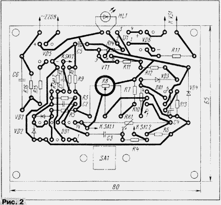
All the elements of a heat stabilizer except triac VS1 and output jacks X1 and x2, mounted on the PCB size 80(65 mm (Fig. 2). The fee is calculated on the installation of resistors MLT (R10 - KIM), capacitors K73-17 (C3 63, C6 to 400 V), K50-16 (C5), km-5, km-6 (the rest). Variable resistor R8 - CP3-4m or CP3-BM. Diodes VD1, VD2 - any low-power silicon, Zener diodes VD3 and VD4 - any small-sized for voltage stabilization 3,3...5.6 V and 7.5 8.2 V... respectively. The switch SA1 - P2K fixed in a pressed state.

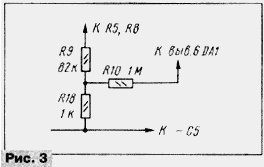
In the absence of the resistor R10 of the specified resistance permissible to change the scheme in accordance with Fig. 3.

Transistor VT1 - any low-power silicon structure p-n-p. Instead of a diode bridges CCA you can use any diodes on the operating current of at least 100 mA for replacement VD6 fit diodes with an operating voltage of 300 V. Directory optocoupler series AO permissible to use alphabetic indices B and C, the triac CU - IN and G.
Capacitor C6 will replace any metal film, for example K73-16, the nominal voltage of at least 400 V.
Led - any visible glow. You only need to pay attention to it installation: the led should be as placed outside the Board, and his the lens is aimed in the same direction as the axis of the variable resistor.
The triac is mounted on a finned heat sink dimensions 60x50x25 mm you can apply heater power up to 1 kW.
Engineering design of the heat stabilizer such as in [4].
When establishing the device you should install stabilization time reduced temperature selection of the resistor R3 and, if necessary, the capacitor C3. For this concluded 12 circuits DD1 and to the negative terminal of the capacitor C5 you must connect the DC voltmeter and when the closed contacts switch SA1 to count the number of pulses in 1...2 min. Further, the results measurements, find the pulse period and multiply it by 16384 - this will be the time work heat stabilizer in the regime of low temperature. In accordance with the necessary variations to these times must clarify the resistance of the resistor R3.
The graduations of the scale of the temperature variable resistor R8 is made without connect the heater, changing the temperature in the room. Setting the temperature in the room, for example, 20 °C, rotating engine variable resistor, mark "20" for the position of the handle, in which there is switching on and off led. As it is necessary to place markers at other points. Graduation facilitates the linearity of the scale.
Range of electrofusion elements of the bridge in accordance with the above the calculation confirmed the high accuracy. In native mode the interval temperature stabilization was 16...27 °C in the low temperature mode -12...23 °C. However, the device stabilizes at 0.5 to 0.8 °C lower temperature than it should be. The fact that the thermistor is heated by the passing current. To reduce the self-heating, preferably use a thermistor with a higher resistance and lower the voltage power.
In the heat stabilizer voltage was chosen as low as possible. When lower voltage at the output of the first element of the generator DD1 chip (pin 10, see [1]) there is a "notch" and the counter starts to work incorrectly. In the same time on the terminals 11 and 12 fronts and the decay of pulses of a clear and steep that once again confirms the avoidance of using the signal output from the first inverter generator [1].
Note: the article [3] discovered typos formula (5) should look like this: Rдоп = (R1R2 + R2R3 - 2R1R3) / (R1 + R3 - 2R2), and the upper formula last column article as: B = ln (R1/R2) / (1/T1 - 1/T2).
Literature
Author: S. Biryukov, Moscow


