


")

Currently released chip trinistorny and triac pulse-phase regulators of the RMS voltage enable you to create compact and convenient device. Most preferred for these purposes semis-Torno chip, since the diode bridge in trinistorny regulators dissipates considerable power that is extremely compact designs it is undesirable because of the limited cooling capabilities.
The article describes a small-sized voltage regulator, made in triac chip.
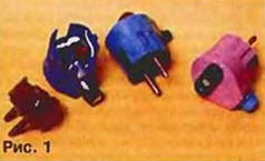
This device is assembled on a specialized chip UAH-1-220, which is a pulse-phase triac voltage regulator. It can be placed directly in the plug loads, such as soldering. However, in practice it is more convenient to use the device in the form of a plug-adapter to the wall outlet for connection to the load. The appearance of a controller shown in Fig.1.
The basic parameters of the chip
- Maximum permissible voltage (peak value), ......400
- Nominal line voltage. In......220
- The load current, max, A......2
- The throttle effective stress, % .....0…97
- The load capacity, W IC without heat sink......250
- chip mounted on the heat sink......400
- The working temperature range,°C......-40…+70
Given the limited conditions of cooling in a compact design power the load of the device must not exceed 100 watts.
The regulator is made according to the standard scheme of the manufacturer, which is shown in Fig. 2. When specified in the scheme the resistance of the variable resistor R1 provided passport throttle voltage.
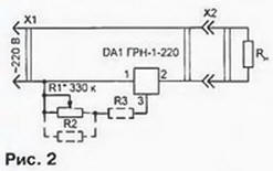
From practical experience it is known that in most cases, for soldering the optimal operating voltage is about 150… 160 V. it is Therefore advisable to limit the voltage change from about 100 to 200…210, to make the tension adjustment smoother. In addition, you may experience problems with the acquisition of the variable resistor of the proper value. To solve these questions is possible by installing additional resistors shown in Fig. 2 by the dashed line. If the throttle would be more correct, you should install an additional resistor R2 whose resistance choose upon establishment, but if it's lower, the resistor R3.
A selection of the advisable to perform before installing the unit. It should be recalled that measure best voltmeter electromagnetic or thermal system, since they only measure RMS voltage. In a pinch the setting can be made using as an indicator of normal lamp filament.
Variable resistor R1 - SP-0.4, SDR-9a or other small. It needs to be sure with linear characteristic of the control (group a). Note, h th when you connect an additional parallel resistor R2 linearity regulation somewhat broken, but significant value it has. Additional resistors must also be small, such as MLT-0,125.
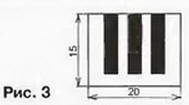
To install the plug in the chip should be revised taking into account the features of its design: chip assembled on a substrate of thin fiberglass. Its findings - continued conductor paths, when they bend break easily and handle them with appropriate care. To enhance design curved pins soldered to PCB from one-sided foil fiberglass thickness of 0.5…0.8 mm, drawing which is shown in Fig. 3.
Cost it is advisable to stick to the bottom of the chip with the help of hot melt adhesive.
The basis of design - the plug with the "ground". For placement details the regulator will have to finalize a few: drill the holes for cover install two-pole socket, remove the "extra" plastic in the body and the plug cover. After mounting variable resistor "sink" into the body and pour-melt adhesive.
Author: Dmitry Turchinsky, Moscow