


")

Setting indoors and out several temperature sensors series AD22100 and collecting the very simple device of a conventional arrow microammeter and a few other details, at any time to learn the temperature at the desired points.
Temperature sensors series AD22100 is produced in packages of two modifications (Fig. 1).
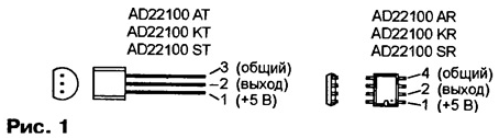
In addition to the design of the hull, sensors with different letter indexes differ working temperature increments: CT (KR) - 0…+100 °C, AT (AR) - -40…+85 °C and ST (SR) - -50…+150 °C. When the 5 V supply voltage current consumption no exceed 0.5 mA.
The output voltage Uвых (between pins 2 and 3 or 2 and 4) depends linearly on temperature sensor housing. Its value at temperature T, given in degrees Celsius can be found by the formula
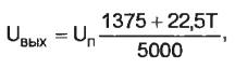
which is fair with supply voltage Un from 4 to 6 V. the Deviation from this the law does not exceed 1 °C (for sensors with indices ST and SR - 2 °C).
Thus, when Un=5 V and T=0 °C output voltage of the sensor - 1,375, changing to 0,0225 In each one-degree temperature. Characteristics of the sensors strictly normalized, so if necessary, they can be connected alternately to the same measuring temperature without additional calibration. In Fig. 2 shows a diagram of a multipoint thermometer, which implements this idea.
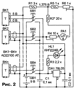
The number placed in necessary places sensors BK1-WCP limited the total current consumed from the battery GB1. Any one of them is connected to the measuring node by pressing the corresponding button SB1-SBn. At the same time the second the contact group button closes the supply circuit of the device. High toughness temperature characteristics of sensors eliminated the need for the amplifier, using as a temperature indicator ammeter PA1 included in the diagonal the measuring bridge formed by the sensor and a resistive voltage divider R1R5R6.
To zero temperature correspond to the zero reading on the microammeter, the total voltage drop across the resistors R5 and R6 must be equal to 1,375, what to achieve with the help of trimmer resistor R6. The sum of the resistances resistors R2, R4 and scope of the microammeter is selected in such a way that each the degree of temperature corresponds to the deflection of the microammeter PA1 1 mA. This allows taking microammeter desired sensitivity, use available on its scale calibrated for temperature readout.
Integral stabilizer DA1 lowers the voltage of the battery until needed for GB1 sensor supply 5 V. HL1 Led is an indicator not only of inclusion device, but the battery status and GB1. While its voltage is normal (6,8…9 V), At pressing any of the buttons SB1-SBn HL1 led to the applied voltage will be more than 8 In 1 and it will glow. The complete absence of illumination of the led demonstrates the need to replace the battery.
In order not to affect the operation of the stabilizer DA1, the current in the circuit to control the selected small, and as HL1 applied led red glow increased brightness. If you install the led of a different color, change the threshold indicator.
Mounting the thermometer is mounted. Most of the details, including one of the sensors (e.g., BK1), can be placed on the Board of fiberglass and strengthen it in the findings of the microammeter RA1. The latter is placed in a body of insulating material. On the front panel of the device, except microammeter, establish the buttons and LEDs HL1.
If the sensors are placed on a distance of more than 1-2 m from the measuring unit, the connecting wires should be shielded. Sensors installed on outdoor or indoors with high humidity, as well as the soldering points the wires to their conclusions necessarily protect moisture-proof, for example, epoxy compound. When measuring the temperature of water or other liquid to protect sensors from its impact should pay special attention.
The author has used small microammeter M 50-0-50 µa. For improve the accuracy of the temperature readout is desirable to use a device with a scale larger size but with the same values of the current full deflection in one and the other side. The fact that the sensors of the series AD22100 can't accept "flowing" in conclusion 2 current of 80 μa, and in this mode they are in this the thermometer operate at temperatures below freezing.
Balancing the measuring bridge is not at zero, and with minimal negative temperature, you can use the micro-ammeter with zero at the beginning of the scale and significantly high current full deflection ("derived" from the sensor current can to reach a few milliamps). It is enough with the help of trimmer resistor R6 to set the voltage in the connection point of the resistors R1, R2 and R5 equal to the output voltage of the sensor at the desired temperature. Naturally, digitization of the scale of the microammeter in this case, you will have to change.
Calibrate the thermometer by placing one of the sensors alternately in cold and hot Wednesday, for example, water with a controlled, accurate laboratory thermometer temperature. When the environment temperature is close to zero (or another when the the bridge must be balanced), pointer of the microammeter PA1 set on corresponding to the reading of the reference thermometer scale with trim resistor R6.
Then carry the sensor in an environment with temperature, as many different from first, wait for the reading to stabilize (the needle of the microammeter should RA1 to stop "creep") and re-set the arrow to the desired division. This time - trimming resistor R4. If the limits of adjustment of R4 is not enough, you should change the value of the resistor R2. The calibration procedure must be repeated several times.
Author: I. Nechaev, Kursk