


")

This device, operating on the principle of measuring bridge, allows for 3…with 4 to determine the operating temperature of the chip, resistor or other parts of radio equipment with precision better than 0.1 C. In many cases it can significantly speed up the repair sophisticated equipment, collected even on chips of CMOS structure. Search defective chips based on the definition of high heat dissipation radiokomponent that, as a rule, is associated with impaired its electric operation.
Measuring ranges, set by the switch SA3, two: 0…+40°C (I) and +10…+30 °C (II). Ranges may be removed by the resistor R9 "setup" in the calibration of the device before measurement or expanded trimmer R6 and R7 in the process of adjustment-constructed device.
High measurement speed achieved by as the thermistor temperature sensor ST3-19 (R10), which has a small mass. Structurally, the thermistor is placed at the end of the casing of a ballpoint pen and is connected to the device is cut twisted two-wire cable length 0,6…1 m. Connector X3 - any.
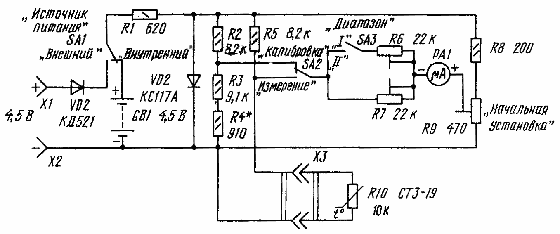
Fig. 1
The device can be powered from an internal source voltage 4.5 V (GB1), and from the outside with the same voltage, connected to terminals X1, x2.
Microammeter RA1 - M1691 on the current total deviation arrow 10 μa, with a zero in the middle of the scale, or other similar, preferably with a large scale. Trimmer resistors R6, R7, and R9 - multi SP5-2 or similar.
To calibrate the device, it is desirable to use the heat chamber with automatic maintenance of the set temperature.
First disconnected from the sensor device is placed in a heat chamber (the cable end is left outside) and it is possible more precisely measure its resistance at 20°C. Then using a digital ohmmeter choose the resistor R4, and if need be, and a resistor R3 such value to the total resistance was equal to the measured the resistance of the thermistor and solder them in place.
Connecting the sensor to the bridge and set the switch SA2 to "Calibrate", and SA3 - in position "I", include the power source and the resistor R9 of the output arrow of the microammeter on average, the zero - scale. The sensor remains in a heat chamber. For the first ("I") measuring range zero division the scale will correspond to a temperature of +20°C.
Further, the switch SA2 is set to position "Measurement" and at a temperature in a heat chamber at +40°C resistor R7 achieve deflection of the microammeter to end right the division of the scale.
For more accuracy, the calibration of the sensor temperature +20 °C and a measurement at the temperature of +40°C should repeat two or three times.
Finally, the switch SA3 is moved to "II" and at the temperature sensor, +10 and +30°C resistor R6 set respectively the start and end edges of the second measurement range.
In the above-described device has a supply sensitivity. But a significant increase in sensitivity will increase measurement error due to the influence of even a weak air circulation.
Author: I. Shelestov, Moscow; Publication: www.cxem.net