Camera specialized television systems usually work on a public the air, and therefore require protection from climatic influences. For this reason most often they are placed inside sealed boxes. Most television chambers (TC) operating temperature range is -20...+55°C, so the boxes necessary to supply the heaters which are switched on when the temperature drops ambient air is below 0°C. unfortunately, certified boxes with enough reliable devices of heating and control of the road. Cheap but very unreliable. As a result, the task of creating a cost-efficient and reliable heaters remains very relevant. Description of one of these devices is proposed below.
The device is designed to operate inside sealed boxes volume 2...10 dm3 , without special thermal insulation, the climate of the middle latitudes of Russia. It is a heater that turns on at lower the temperature in the box and maintain it at a certain level with error (taking into account the inhomogeneous distribution inside the controlled volume) not more than 1...3°C.
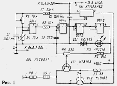
Running the heater on the principle of a threshold temperature regulation. It the electrical diagram is presented in Fig. 1. Primary unstabilized the source voltage u n and m=20 is used to power only to the heater and stabilizer on a chip of DA1. The control device TC is powered stabilized voltage u pit.stub=12, which is formed at the output of DA1.
It should be noted that the temperature instability of output voltage in three-terminal integrated stabilizers more than other stabilizers types. This instability manifests itself when self-heating of the chip CRED the flowing current.
TC different types consume a current of 0.1...0.2 A, so the stabilizer DA1 had to provide a hinged heat sink area of about 30 cm2. Your expansion voltage instability u pit.stub must be considered when choosing the threshold scheme of the heater control.
Converter temperature - voltage is made in the form of a voltage divider the resistors R1, R2 and the thermistor R4. The divider is loaded by the input the resistance of the logic element DD1.1, amounting to about 1012 Ohms, so the operating current of the thermistor R4, equal to about 0.5 mA, irrespective of load divider.
The function of the threshold device performs an element DD1.1 DD1 chip, performing a comparison of the voltage drop across the thermistor R4 level input voltage Uпор2, which works very DD1.1. For the two types logical elements value of Uпор can be determined by static transfer characteristics presented in Fig. 2,and. Voltage Uпор located in areas of characteristics, which are enclosed between levels minimum voltage logical units U1мин and the maximum voltage logic zero U0макс. Corresponding to these sections of the input intervals threshold voltages of logic elements are relatively small, so you can approximately assumed that the Uпор corresponds to the midpoint of this interval, i.e. The Uпор=0,5 U Pit.stub. Such approach allows to determine the Uпор with an error of the order of tens of millivolts.
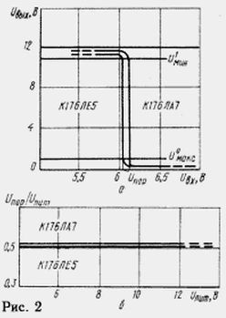
Due to thermal instability of the voltage u pit.stub. in the interval working temperature TC, it is important that the ratio of the amount of Uпор threshold element to the voltage drop across R4 is equal to R4Uпит.stub./(R1+R2+R4), remained unchanged. Logic elements series CMOS well meet this requirement that demonstrates Fig. 2,b. Shown therein indicate that the the ratio of Uпор/u pit.stub.=0,5 persists over the whole range of voltages power allowed for logic elements circuits series C.
Since the inputs DD1.1 operates slowly changes following changes temperature the voltage drop across the thermistor R4, the element DD1.1 long is in the active mode, as reinforcing the useful signal and interference. For noise suppression on the input and output DD1.1 filter turned on - R1R2R4C1 and R3C2 respectively. The elements DD1.2, DD1.3 and DD1.4 and further enhance form the useful signal coming from the output of the filter R3C2.
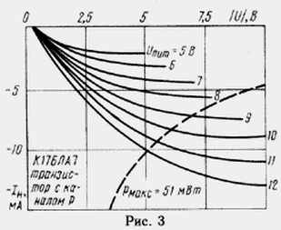
The output signal of the element DD1.2 controls the reference voltage source, which is a parametric stabilizer made on the Zener diode VD1 and the led HL1.A distinctive feature of this source is the lack of ballast resistor and power it directly from the exit of the element DD1.2. It possibly due to the relatively large output impedance CMOS transistors in the elements series chipset C. Eats parametric the stabilizer through the transistor with a channel of p type. Output volt-ampere the characteristics of this transistor for logic elements from the chip CLA shown in Fig. 3. The working section of these characteristics is limited the hyperbole allowable power dissipation chip CLA (pmax). On characteristics: the |U| is the voltage drop across realnom transistor, and In - current, flowing through it. Since the voltage drop across the Zener diode VD1 and the HL1 led is approximately 7 V, for u pit.stub=12 In the working position point of the transistor corresponds to |U|=5 V and IR=10 mA. This output the resistance of the logic element will be approximately 1 kω, and the p-channel the transistor will be for diodes VD1 and HL1 current limiter. Self supporting the voltage is generated on the engine, the variable resistor R5.
The heater is a current source, collected on included in the scheme Sziklai transistors VT1, VT2, the resistor R7 and ballast resistors R8, R9. When adjusting the reference voltage value of the collector current of the transistor VT2 may to change from zero to 1 a, And the dissipated power to be 18 watts. To to ensure reliable operation of the heater in such circumstances, an important current stabilization the collector of transistor VT2 to a temperature of approximately +80°C. This is achieved using the following schematic and design solutions.
To reduce instability of the collector current because of changes in the fall the voltage at the junction between the base and emitter during heating it is equipped with a transistor heat sink, the surface area of which is selected such that when in this box with the current collector 1 And the transistor VT2 is not overheated above +80°C.
Now let's talk about the work of the heater. Let the initial state of the temperature in the box above ambient air temperature and the threshold temperature set the adjusting resistor R2. Thus the resistance of the thermistor R4 is little and the voltage drop is less than the Uпор. In this case, the output element DD1.2 there is a low logic level and the current through the heater is not flowing. Over time, the temperature in the box due to its cooling will be reduced. The resistance of the thermistor R4 and the voltage drop on it will start to grow and, when the voltage reaches the level of Uпор, the output DD1.1 will be formed flat front low voltage level. In the process of forming this front will change the output status of logic elements DD1.2, DD1.3, DD1.4, due to which will switch the device for the heater control. The output element DD1.2 set the voltage corresponding to the voltage stabilization VD1 and the voltage drop across the led HL1, and through the transistor VT2 will flow specified current.
The heat sink VT2 warmed up the air in the box. The temperature of the thermistor R4 will begin to grow and the voltage across it to decrease. When you re reaching the approximate equality of the voltage drop across the thermistor R4 and the voltage of Uпор the control unit will switch to its original state, and the current through the transistor VT2 again will stop. These switch are repeated at fixed intervals, duration of which are determined by the characteristics of the heat exchange box. In this case the air temperature in the box will vary within the values specified the position of the slider of the resistor R2.
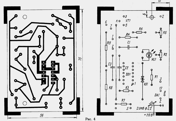
The main functional units of the described device is placed on the circuit Board (Fig. 4). Out Board is the transistor VT2. To provide just warming up of box volume, the VT2 transistor and thermistor R4, you must post on may a greater distance. Heater involves the following elements: transistors VT1, VT2 in plastic housings, chips or CLE CLA (DD1) and KIND in a plastic housing (DA1), resistors R1, R3, R6 - R9 - MLT, S2-33, MT, or their analogues, R2, R5 - SP5-2, R4 - MMT denominated 8 12... ohms, capacitors C1-C3 - km of any group.
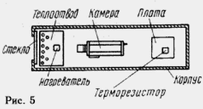
Placing the heater inside the Cabinet TC shown in Fig. 5. Transistor VT2 installed on the heat sink of aluminum alloy dimensions 120x70x3 He mm. mounted on a mica gasket with PTFE bushing, insulating mounting screw, and therefore has no electrical contact with the heat sink. In turn, the heat sink has no metal fasteners, directly attaching it to the case body. On the edge of the heat sink, facing the window Boxing, there are two rows of holes that improve circulation air. To produce heat elements DA1, R8, R9 little or no influence on thermistor R4, it is elevated above the motherboard at a height of 10...15 mm.
Adjusting the operating mode is the shutter speed open box at a temperature equal to the desired turn-on threshold, in the absence of current in the heater during 20...30 min. to avoid falling into Boxing moisture. By installing in it the desired temperature, the adjusting resistor R2 is necessary to achieve the illumination LEDs HL1, stopping the regulation in achieving equality of voltage at the thermistor R4 voltage Uпор.
Author: G. Pilko, Kiev, Ukraine


