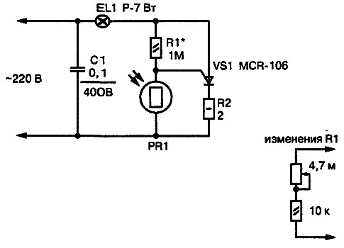
The figure shows the appearance of auto lamp, triggered when darkening of the working surface.

The practical application of the device finds in automatic backlight signs with the street name and house number. Incandescent lamp mounted inside a plastic housing plate number house, and the elements of the device in the wall of the house in a closed and protected from moisture body. In normal light (when light) the lamp does not light. When dusk natural light falls, and incandescent lamp lit, illuminating the sign. The photo sensor is a photoresistor, which through the lens penetrates the external light flux.
PR1 - photoresistor brand RFT-01 is used as the photosensor in the controller of rotation of the turntable "Arcturus-004". Instead the quality of the photoresistor may be possible to apply also photoresistors, installed on your the optocouplers of the CES-1. Under the illumination of the photoresistor (bright sunlight) it the resistance drops to 12 ohms and the shunt switch control electrode - the cathode of thyristor VS1. In this case, the thyristor is closed and de-energizes the lamp filament EL1. For such illumination is sufficiently low-power lamps. Apply in the device is more powerful bulb is impossible because of the danger of overheating and melting of the plastic cover plates.
With incandescent lamps 1 W (backlight refrigerators, sewing machines and other household illumination devices) device was used continuously for two days (with constant the lamp EL1), the temperature around the bulb was not raised above +35 °C, which is quite acceptable. In low light the sensor (which happens in the dark, the resistance of the photoresistor is high (more than 1 IOM). The current passing through a current limiting resistor R1, it is sufficient for opening of the thyristor.
Establishment. To increase the photosensitivity of the node can be replaced by fixed resistors R1 equivalent circuit as shown in Fig. 2.12 (below) by typing in the electronic unit sensitivity adjustment. Thus, the change in resistance resistor R1 reaches respectively increase or decrease the current through R1. For the same reason will be the change in the potential at the middle point of the divider voltage R1PR1. If you increase the current through R1 (reduction of resistance) repeatedly increases the sensitivity of the node to outer darkness. Now lamp works faster at dusk (includes backlight).
When the decrease of the current through resistor R1 (increase of resistance) will happen reverse - the lamp becomes more sensitive to outside light on and off illumination even at low impact on the working surface of the image sensor light stream. Variable resistor for adjusting the sensitivity threshold apply either (after adjustment by measuring its equivalent resistance, R1 replace constant). To preserve the ability to adjust, fit multi-turn variable resistor SDR-BW or similar compact trimmer.
Phasing inclusion in the network 220 to the device are not principal.
About the details. The thyristor VS1 is applied type MCR-106-8 (marked MCR-106). It can replace other thyristors of the company Motorola. This designation is given not accidentally, as the thyristor for this scheme you can choose any other, guided reference materials on the electrical characteristics of thyristors and triacs company Motorola (listed in the Appendix to the book).
Capacitor C1 type MBM or similar at a working voltage of 300 V. With increasing power load is more than 60 watts, you need to install the thyristor on to the heat sink.
An electrical circuit it is possible to assemble for use in other designs as simple photosensor. While taking into account the following points.
The thyristor VS1 replace domestic triac COG.
The constant resistor R2 exclude from the scheme, instead it set the jumper. The resistor R1 is replaced by another with the power dissipation of 2 watts and the resistance 12-18 com. Or an equivalent scheme (if required sensitivity adjustment and threshold photosensor) with the same total resistance. Photoresistor PR1 is the same as in the basic scheme. When changing to a different type of resistance resistor R1 is necessary to select advanced, and in the other within.


