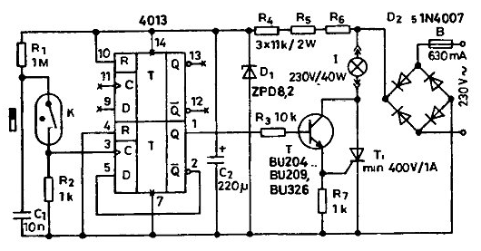
The proposed device can be used for ancillary facilities in the apartment (in the bathroom, the closet, the pantry, etc.). The opening and subsequent the closing of the door switches the light on and following opening and closing disables it. To do this on a door jamb, you need to install the switch. and the door itself is a permanent magnet which holds the reed switch in a closed condition. when the door is closed. Easiest way for this purpose use a pair the magnet/ reed switch from the existing 8 sale of burglar alarm devices.

If the door is closed, the clock input From the bottom of the trigger through the closed reed switch To high level is applied (Boolean T). If the door opens, and then again closes, there is a change of levels"1"-"0"-"1". D-flip-flop is triggered by drop the "0" to "1", and in response to a rise in the level he "overturned" Because the inverse output of the trigger is connected to the input D of the trigger operates in a counting mode, i.e. each time you drop the "0" - "G at the input it changes its state on the opposite.
After the switch trigger high level from its output opens through the transistor T the thyristor Ti. which commutes lamp I. the Thyristor opens in the beginning of each half cycle of the mains voltage, while the output of the trigger maintained a high level. The lamp is supplied pulsating (rectified) the voltage through the diode bridge diodes D2...05. Subsequent opening and the closing of the door throws the trigger, its output is set to low level, and the lamp goes out.
The power IC is provided by the parametric stabilizer Zener diode D1, operating current for which to set the resistors R4, R6, the Capacitor C2 eliminates interference nutrition, and C1-inrush-voltage actuation of the reed switch.
The device can collect the mounted Assembly on a piece of fiberglass or Micarta and place in a suitable plastic box in which to consolidate somewhere on the doorjamb or near the lamp so that it was not evident eyes.
Since the power supply is carried out according to the transformerless circuit, for adjusting caution must be exercised. Best logical part (to the transistor) first, to debug separately. powering from the DC power supply 7.. 10 In (several batteries) Terminal of the source connected to the capacitor C2, and a Zener diode D1 is temporarily disconnected. Achieving reliable operation trigger when opening and closing doors, you can connect the power section.
The 4013 chip you can replace domestic KTM. the transistor needed high voltage with permissible operating voltage of not lower than 300 V. for example. CT. CT. CTA. Diodes D2...D5 - CDN, P Thyristor can take CUZ.
In the Zener diode will fit any from D, KC175...KC1Q1.
Literature
Author: A. Belsky


