


")

The utility agriculture plays a significant role backyard greenhouses. But green cucumber or flowers for the holiday require much labor and skill. One of the main parameters for growing winter greens is lighting. So, for example, to cucumber light day should be 16 hours, and tomatoes for 18 hours [1]. In some greenhouses practiced round-the-clock coverage. However for normal physiological development of plants is required a few hours of complete darkness.
Existing machines for greenhouses [2] allow programming on and deactivation of supplementary lighting in a fixed time. For example, from 18.00 at 22.00. However, as we know, the maximum change in light day in the days close to the equinox (autumn or spring). This is due to the fact that the passage of the sun the celestial equator it has the maximum angular velocity. And on the contrary. The minimum change in of the day in the days close to the solstice. Itself the name speaks about staying sun. The sun is in the highest (lowest) point of the orbit (the Ecliptic) and has a minimum angular displacement. This is a small the retreat in the course of school astronomy provides a better understanding of why autumn day decreases, and in the spring increases. So the main drawback of the existing machines for greenhouses is fixed time on and turn off lighting and supplementary lighting.
Offer automatic "daylight" includes coverage upon the occurrence of dusk and turns off at the end programmed time light day. The time of daylight set from 12 hours to 15 hours via one hour with two switches.
The advantages the offered machine is possible to include the fact that the installation the photoresistor is not critical to the penetration of direct light from lighting of the greenhouse. Fixed and the uncertainty of the transition process time of inclusion counter. There is a possibility enable (disable) lighting the manual mode. This machine can to find the application when you turn on lighting for the aquarium and other cases where you need an extension light day, for example, in the house or in livestock house.
Principal scheme machine:
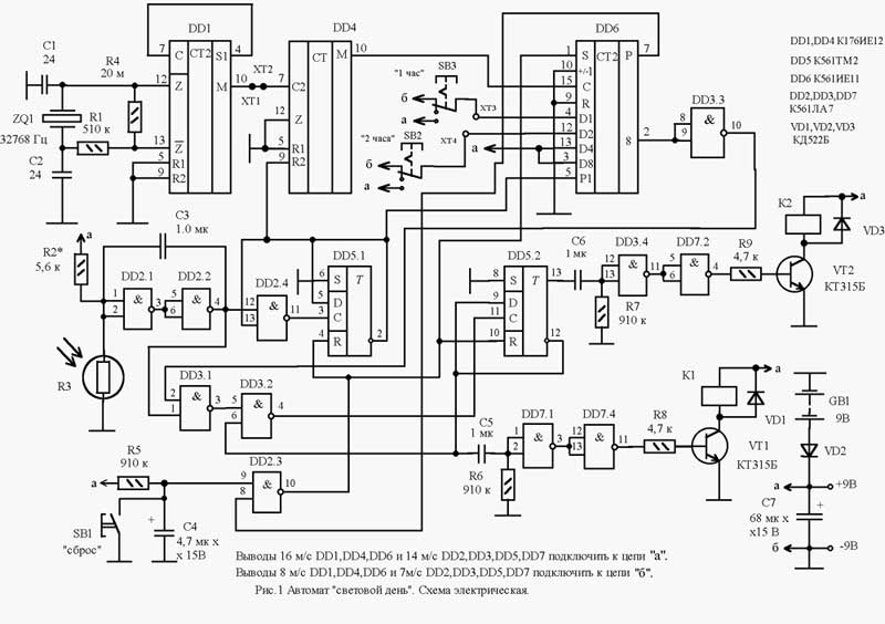
The machine is from the master oscillator and divider pulses on the chip DD1. Divider 60 DD4 and reverse counter with pre installing DD6; shaper pulses on the elements DD2.1, DD2.2; control unit on the chip DD5, DD2.3, DD2.4, DD3.1, DD3.2, DD3.3. Two shapers of pulses of high duration consisting of differentiating chains C6, R7 and C5, R6; and inverters on the elements DD3.4, DD7.2 and DD7.1, DD7.4. Keys on transistors VT1, VT2 and relays K1, K2.
Machine work based on the programming time of daylight by install the code on reverse counter DD6 with subsequent subtraction with a resolution of one hour. Run counter happens the morning after illumination of the photoresistor.
After turning on the voltage at pin 9 element DD2.3 is a logical zero, and at the conclusion of the 10 - logical unit. The level of logical units with o 10 resets the trigger DD5, and pre the installation of the meter DD6.
Quartz oscillator and frequency divider chip DD1 was built according to the standard scheme enable start to work immediately after voltage. With output 10 DD1 pulses with a period of 1 minute is input to the divider 7 60 DD4. However, the counter does not consider since the reset input (pin 9 DD4) and the carry-in input (pin 5 DD6) served prohibiting level logical units with output 2 trigger DD5.1.
In the dark days photoresistor R3 has a large resistance against the resistor R2, therefore the conclusions 1, 2 chip DD2.1 present the level of logical units, and the counting inputs 3,11 trigger DD5 - a logic level zero.
In the morning, when the light increases the resistance of the photoresistor R3 decreases and the voltage at conclusions 1,2 DD2.1 begins to approach the level of logical zero. A moment of uncertainty between the level of ones and zeros is smoothed by a capacitor high capacity C3, which slowly recharged. Level zero with output 4 DD2.2 arrives at the inputs 12 element DD2.4 and 1 element DD3.1. But if the element DD2.4 open unit with output 2 DD5.1, the element DD3.1 on the contrary, closed with zero output of inverter 10 DD3.3 (preset fourth discharge counter DD6 per unit). Thus, the trigger DD5.1 overturned, allowing the passage of pulses using counters DD4, DD6, and prohibiting the the passage of impulses through the element DD2.4. Further changes illumination of the photocell is not affected to operate the machine until such time as the deductible amount of pulses from counter DD6 reaches changes level in fourth grade. It will occur no earlier than five hours or more (up to 8 hours), based on the submitted levels in point HT, HT. This is achieved good protection channel enable (off) the lights in the daytime time.
In the evening, when natural light decreases, resistance the photoresistor R3 increases, and conclusion 3 element DD3.1 will appear a logic level zero. On the counting input 11 of flip-flop DD5.2 appears unit, the trigger capsize and close the element DD3.2 to pass the pulses. So further adjustments to lighting the photosensor does not affect the operation machine until, until over a set time.
After rollover trigger at pin 13 DD5.2 appears the level of logical the unit that comes on the pulse shaper large duration consisting of differentiating chain at C6, R7 and the two inverters on the elements DD3.4, DD7.2. From the output of the pulse shaper duration of 0.5 seconds opens the key on the transistor VT2. Short relay start K2 (Fig. 4), closing the contacts 2,3 K1.1 and feeding power to the starter K3. The self-locking actuator contact K3.1 and closes contacts K3.2 - K3.4. Depending on the situation switches SA1-SA3 or enables the different lighting line EL1-EL3.
After set amount the pulses at the counter will DD6 deducted, the carry output P (conclusion 7) will be a logical zero. On the setting input S (1) counter and DD6 the reset inputs R (4,10) triggers DD5, through inverter DD2.3 will be served unit. Happens preset counter and reset triggers. Differentiating chain C5, R6 and inverters DD7.1, DD7.4 is formed the stop pulse, the relay K1 will work and will disconnect the contacts 1,2 K1.1. Contactor K3 abastecida, open contacts K3.1 - K3.4 and the light will go out. It will happen at night and in the morning the work cycle of the machine I will repeat again.
Temporary chart of the operation of the machine in key points given in Fig. 5. Here time t1 is the moment of inclusion the machine in the morning, t2 - time of inclusion lighting in the evening, t3 is the time finishing the count and off machine at night.
When conducting work in the greenhouse sometimes the need to extend coverage, it is easy to make buttons start SB4 and "stop" SB5. But in don't forget after light is turned off a short press of the button "reset" SB1 to install machine to its original state. With the same purpose, after installation of the gun in the dark or early in the morning, click on the "reset" button SB1. When weak light day light you can turn in manual mode, but before I leave greenhouse, if you have enough light, light needs to be switched off. In otherwise you'll need short to make a shade photoresistor to trigger automatic shut-off light.
As backup power is used battery type "crown", connected through the diode VD2. When a current consumed in the real account about 0.5 milliamps ( relay - 20 mA) standby the battery lasts for the whole season.
Photoresistor better to locate in a dark corner the greenhouse, taking care to it did not get light from the moon and car headlights at night days. It is also desirable cover rare mesh from insects and flies.
Establishing devices with check the health of the generator and dividers on the chip DD1. It you can make even the tester, checking the availability of used pulses at pin 4 and minute pulses at pin 10 of the chip DD1. Then there is the signal at the output 4 DD2.2, primenyaetsa photoresistor R3 and installed the resistance of the resistor R2 so that to the pin 4 has been established the level of logical units. The resistance of the resistor R2 depends from the level of the selected light which should work machine, and from resistance lit applied to the photoresistor. Open jumper 1-HT and contact HT connect pin 4 DD1. If you have a frequency counter with jog input, connect it concluded 9 DD4, and to the counting input contact HT. Turn on your desktop the lamp and close the photosensor. After finishing the count on the counter should be highlighted numbers are equal, offered for installation the inputs of the meter expressed in DD6 minutes. If you don't have jog input, connect the counting input of the frequency counter to pin 10 DD4, but then the resulting number will be expressed in hours. If not the frequency, at the moment of inclusion table lamp count the time from the exact minute and the number minute pulses applied to counter DD6, must equal the number, on display in binary code installation inputs. For reliable determine the stop point counter (by eye) to the relay contacts K1 via 1kOhm resistor plug the red led. After health checks the device, remember restore the jumper 1-HT.
Contact HT, HT connect the switches SB3, SB4 latching type P2K so that when the down switch on contacts were served high level, when released is low. These switches installed extra time with increments of one hour. Pre-installation counter DD6 is performed for 12 hours. While pressing the button SB3, pre-install added for 1 hour, and when pressed button SB4 - 2 hours. Thus, the maximum time of daylight is 15 hours. If the installation time buttons SB2, SB3 produced during the day, then new the value of the "daylight" will be only the next day. It must be remembered that when working counter 561IE11 in reverse mode momentum transfer at pin 7 appears at the moment of transition the state of the counter through zero.
All resistors in device MLT-0,125, diodes KDB can be replaced by any pulse or rectifier. The capacitors C3, C5, C6 type can CM replace electrolytic capacitors by placing a plus to the trigger pin DD5.2 and to the photoresistor. The capacitor C4 type K53-1 can be replaced by any an electrolyte. Transistors can KT315B replaceable silicon low frequency with a suitable voltage emitter-collector and power. Counter DD6 can CIE to be replaced by CIE, but pin 9 must be connected to high level for accounts in binary mode. Chip DD2, DD3, DD7 CLA and DD5 KTM can be substituted with serii. Relays K1, K2 type RAS passport RS4.569.426 not meant to be switching AC voltage and current and selected by the author from available. Many years the operation of these relays in similar modes showed them sustainable work. If there the ability, the best replacement would be relay type RAS passport RF4.500.341. You can replace the relay type RES15 passport RS4.591.003. Photoresistor R3 used by the author of the optocoupler OAP with the removal of light bulbs and fill with epoxy the light-sensitive layer to reduce atmospheric effects. Optocoupler contains two OAP photoresistors (pins 2,6 and 3,5) it is better to connect in parallel. Can use any photoresistor with tuning (as mentioned above) resistor R2. Quartz ZQ1 type RC can be replaced by any taken with a faulty quartz hours, and if the frequency is two times lower, instead of pin 4 need to take DD1 conclusion 6.
Relays are attached to two copper Board wires through the foam, and quartz is installed using rubber gasket.
Cost better set in the shielding housing. The connecting cord to the photoresistor length 1 meter must be escaped.
Literature
Publication: www.cxem.net