


")

The proposed device is intended for switching on and off (including remote) incandescent lamps, heaters and other devices powered from a household 220 V, and represents a purely resistive load power up to 500 watts. The circuit breaker depicted in Fig. 1.
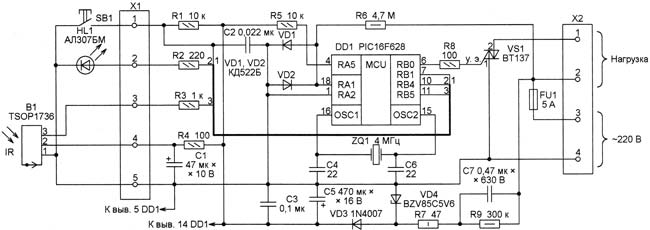
Fig. 1
AC voltage 220 through the fuse FU1 is supplied to the feeding unit, assembled from elements of VD3, VD4, NW, C5, C7, R7 and R9. Stabilized voltage of 5 V from the capacitor C5 is powering the microcontroller DD1 and detector B1. The microcontroller working on written in a program that analyzes the signals from the photodetector to the input RB5 and from button SB1 input RB1, and sensor zero-phase line voltage by the resistor R6, diodes VD1, VD2) to the input RA1. Signals generated at the outputs RB0 and RB4, the microcontroller controls accordingly the triac VS1 and led HL1. The switch changes its state to the opposite each time you press the SB1 or the button on the remote control. Two options are proposed for the program. Working on the first one (file irs_v110.hex), the microcontroller stores the current state of the switch and in the event of a temporary power outage at the resumption of its supply restores this state. When using the second version of the program (file irs_v111.hex) recovery voltage always puts the switch in its off state. HL1 led illuminates when the load circuit is open. This is useful for lighting equipment. Diagram of remote control switch is shown in Fig. 2.
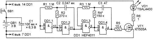
Fig. 2
It is powered by two battery cells AAA. When you press the SB1 starts the generator of pulses with a duration of about 18 MS, assembled on the logic elements DD1.1 and DD1.2. These pulses control the pulse generator at a frequency of 36 kHz on the elements DD1.3, DD1.4. The burst pulse from the output of this oscillator is fed to the gate of the transistor VT1, in the chain of flow of which is included IR emitting diode VD1. The establishment panel is as simple as configuring the generator on the elements DD1.3, DD1.4 at the frequency of 36 kHz (resonance frequency of a sensor B1 in the circuit breaker) selection of the resistor R4. When properly configured, the maximum range of the remote control switch. The printed circuit Board of the switch depicted in Fig. 3.
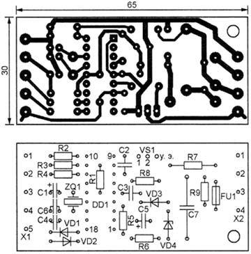
Fig. 3
Triac VT-600 mounted on a heat sink of aluminum plate size 65x15x1 mm. a Replacement for this triac is possible to choose from among similar devices series VT, VT. Zener BZV85C5V6 replaced by another compact with voltage stabilization 5.6 In, for example KSG. Instead of the photodetector TSOP1736, another suitable used in the systems of control TVs and other consumer electronic devices. Centre frequency bandwidth of such a photodetector may be in the range of 30…56 kHz, so the remote control will be set to this frequency. If you need to extend the zone of sensitivity of the switch in a horizontal plane, instead of a single photodetector can be set two, sending them in different directions. With the pins 1 and 2 of the two photodetectors are connected in parallel directly, and pin 3 via a resistor of 1 kOhm. A common point of resistors is connected to the contact pads 3 of X1, and the resistor R3 in the circuit breaker is replaced by a jumper. The printed circuit Board of the remote control is made according to the drawing shown in Fig. 4.
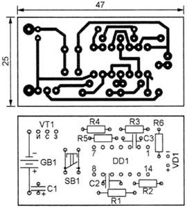
Fig. 4
Here as VD1, you can use any IR emitting diode from the remote appliance. Chip HEF4011 replace similar domestic KLA undesirable. At low voltage it runs erratically. In Fig. 5 shows the appearance of the boards of the switch and the remote control.
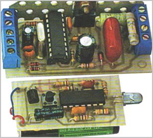
Fig. 5
Download the program of the microcontroller
Author: S. Ivanyuta, Stary Oskol, Belgorod region; Publication: www.cxem.net