In frequently visited areas to save energy, convenient to use capacitive relays for lighting control. When you enter the room, if necessary to turn on the light, go close to the capacitive sensor, which emits a signal capacitive relay, and lamp will turn on. Leaving the premises if you need to turn off light, go close to the capacitive sensor on off switch, and the relay turns off the lamp. In sleep mode, the device consumes a current of about 2 mA.
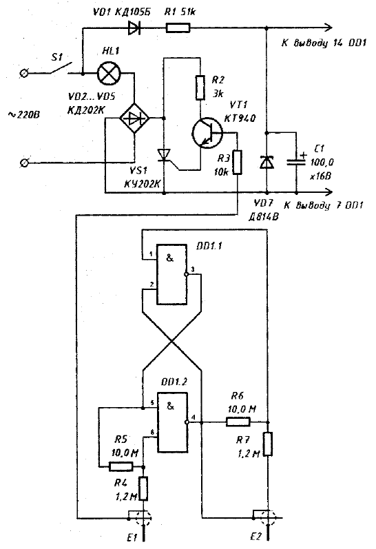
A schematic diagram of a capacitive relay shown in the figure.

(click to enlarge)
The device according to the scheme similar to the time relay, which has the timing node replaced by the trigger logic elements DD1.1, DD1.2. When you turn on the toggle switch S1 through the lamp HL1 will leak current, if the base of the transistor VT1 output element DD1.1 receives a high voltage level. Transistor VT1 in this case open and SCR VD6 opened at the beginning of each half period of the voltage. The trigger is switched from the capacitive leakage current, when a human approaches on some distance to one of the capacitive sensors, if switched from an approximation to another. When you change voltage high level the base of the VT1 transistor on the low voltage SCR VD6 is closed and the lamp will go out.
Capacitive sensors E1 and E2 represent the segments of the coaxial cable (for example, RC-100, PCM-2), with the free end on which a length of about 0.5 m removed screen. The insulation from the Central wire should not be removed. The edge of the screen should isolate. Sensors can be attached to the door frame. The length of unshielded part of the sensors and the resistance of the resistor R5. R6 is selected when establishing device. to trigger reliably switched with the passage of man on a distance of 5...10 cm from the sensor.
When creating a device, you must follow precautions, as elements of the device are at mains voltage.
Author: S. Labkovich, Minsk


