


")

Traditional switching circuits for fluorescent lamps are designed for their food alternating current of industrial frequency. Today becoming more common receives power such lamps with high-frequency current, which eliminates flashing and improves the reliability run. Eliminates the need for bulky the capacitors and chokes on steel cores, often publishing unpleasant buzz. The proposed high frequency unit is small in size, contains the minimum number of winding elements, simple and affordable for repetition.
Block layout is designed for powering fluorescent lamps OSRAM L13W with the diameter of the bulb 16 mm, shown in Fig. 1.
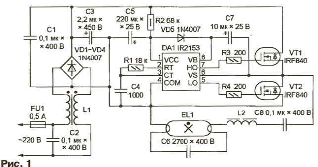
Through FU1 fuse link and noise filter C2L1 mains voltage is supplied to the diode bridge VD1-VD4. The inverter on the chip IR2153 (DA1) and IRF840 FET (VT1, VT2) converts the rectified voltage into a symmetrical rectangular pulses. Detailed information about the IR2153 chip and the transistors of the series IRF can be found at the site of the manufacturer <www.irf.com>.
The frequency of the pulse depends on the values of the elements of timing chain in R1C4 the present case is 33 kHz. Between the pulses at the outputs BUT LO and chips, administering field transistors VT1 and VT2, automatically kept pausing 1.2 μs. This prevents the simultaneous opening transistors flowing through them "through" current.
The supply voltage of the chip DA1 is supplied to the terminal 1 through the quenching resistor R2, and an internal Zener diode prevents the increase of the potential difference between pins 1 and 4 over 15.6 V. In operation here V. 9-10
The output voltage of the inverter is supplied to the lamp EL1 through a separation the capacitor C8 and the ballast choke L2. The purpose of the latter is similar ordinary used in the circuit of lamp current frequency of 50 Hz, but since the frequency in this case is much higher, the inductance of the inductor, its size and weight much less. The capacitor C6 forms the circuit of the heating of the filaments of the lamps.
Unit assembled on a printed circuit Board (Fig. 2) dimensions 100x25 mm.
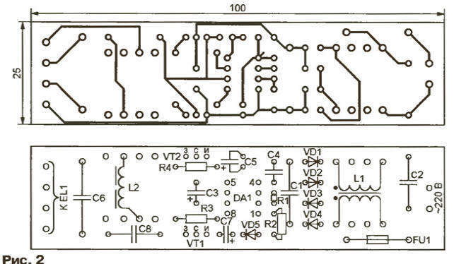
Capacitors C1, C2, S8 - K73-17, C4 and C6 - C-2, oxide - K50-35. Chokes L1 and L2 are wound on the magnetic cores Sh ferrite M2500NMS or MNM. Winding of the inductor L1 contain 200 turns of wire sew-2 0.1 mm and wound in isolated sections frame. Half of the magnetic circuit of the throttle stick together without a gap. Winding inductor L2 is 220 turns of wire sew-2 0.22 mm. In its magnetic circuit required non-magnetic gap, the thickness of which (0,3…0,5 mm) is selected empirically by the brightest glow lamp.
Diodes VD1-VD5 can be replaced by any other on the current of at least 0.5 A and return the voltage of At least 400, for example, KGA-CDV, CDV-CDD. In this case the size of the PCB will have to increase. Replacement transistors IFR840 possible on IRF830, IRF820, but will lead to a deterioration of their thermal regime due to the larger the channel resistance.
Making the unit small changes, can be powered from him and more powerful lamps. For example, in Fig. 3 shows how to connect two lamps LDC-20-2. In this case the cross section of the magnetic circuit of the inductor L2 is increased to 6x6 mm, wire diameter up to 0.4 mm, and the number of turns is reduced to 120. The inductor L3 is identical to L2. On similar to the magnetic coil and the inductor L1, increasing the wire diameter to 0.3 mm.
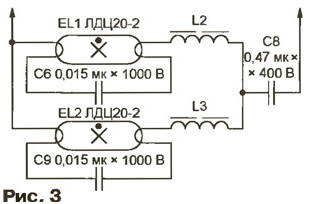
The capacitance of the capacitors C1 and C3 (see Fig. 1) increase to 0.68, respectively, and 10 UF, and the transistors VT1 and VT2 are provided with heat sinks and a minimum area of 40 cm2. You must also be increased to 2 And the actuating current of fuse FU1 and rupture of one of the network cables to install the resistor 4.7 Ohm power not less than 5 watts (e.g., wire) to limit the current charging the capacitor C3 in the time switching the unit.
Author: A. Taraz, St Petersburg