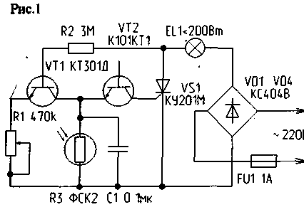
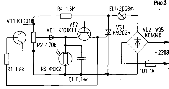
Regulators (Fig. 1,2) allow you to perform two functions: to automatically maintain a predetermined level of illumination regardless of changes in the level of ambient light and smoothly asked to adjust the light level. Observed properties of controllers you can use them to maintain a constant illumination of corridor sites, photo printing, job heat (light) mode in installations of industrial and domestic purposes (incubators, aquariums, greenhouses, thermal and PhotoStitch, etc. devices).
The light emitting element (bulb) power up to 200 watts can be included in the load circuit of thyristor DC (Fig.1, 2) or by a variable - gap in the line cord.

The operation of the thyristor is supplied from RC relaxation oscillator using avalanche transistor VT2 (CCT). In the initial moment of time the charge of the capacitor C1 is supplied from the positive half cycle voltage from the anode of the thyristor VS1 across the resistor R2 and the transistor VT1 (Fig. 1) or resistors R2 and R4 and the diode VD1 (Fig. 2). In parallel with the capacitor C1 connected sernistokislogo foetoprotein type FSK-2, the resistance in the dark is greater than 3 MW. Thus, if the photoresistor is in the shaded area (in the absence of optical communication between the emitter EL1 and the photoresistor R3), the latter almost no shunt capacitors With 1.
When the voltage on the capacitor plates exceeds 8 V, avalanche breakdown occurs of the VT2 transistor and discharge the capacitor to the control electrode of the thyristor VS1. The thyristor current half cycle of the mains voltage to the incandescent lamp is energized network. For each subsequent half cycle of the mains voltage, the process is repeated. The lamp stands out to 95% input power, which is characteristic of all types of thyristor and triac controllers. If the illumination of the photoresistance to increase, its resistance decreases to 200 ohms and less. Since foetoprotein connected in parallel to the storage capacitor C1 of the generator, bypass surgery reduces the rate of charge of the capacitor and the delay time of the thyristor. As a result, the incandescent lamp in each half cycle begins to turn on with a delay proportional to the light level at the point of location of the photoresistor. Accordingly, the total illumination is stabilized at a certain (defined) level. Potentiometer R1 is included in the emitter circuit of the transistor VT1 (Fig. 1) or R2 connected in parallel with the plot of the collector-emitter of the transistor VT1 (Fig. 2), are intended to set maximum light levels and allow you to smoothly adjust the specified level.

If necessary, the device can be converted to a thermostat that works on a similar principle. When mounting the unit should be located such photoresistor a way that the light from the bulb directly falling on the working platform of the photoresistor, because otherwise you may experience generating flashes of light whose frequency phenomenon (optical feedback) can be used to generate light pulses, determining the distance between the reflecting surface and the light emitter/light receiver, in various electronic devices.
Author: M. Shustov, Tomsk; Publication: N. Bolshakov, rf.atnn.ru


