This device is designed for smooth on and off delay lighting in a room. Its peculiarity is in sleep mode it does not consume energy from the network. This is especially important for areas that are frequented not too often, for example, for garage.
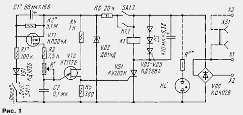
Schematic diagram of the present machine is shown in Fig. 1. It can be installed to replace a conventional light switch. It works as follows. In the initial state, the switch contacts are opened and SA1 through the device occur only leakage current of SCR VS1 and current indicator lights HL' (a fraction of a milliampere). The lighting is switched off. When the closure of the contacts of the switch SA1 of the supply voltage is supplied to the generator pulses collected on the unijunction transistor VT2. However, it is not working will be as long as the voltage on the capacitor C1, charging through the diode VD1 and the resistor R1 reaches a level sufficient to open the transistor VT1. As this transistor opens, the output of the generator will start to receive the pulses, which can be shifted in time from the end to the beginning of each half period of the mains voltage. The pulses will be open SCR VS1. In the result of the voltage on lighting the lamps begin to gradually increase and after a few seconds will reach its nominal value.

The current flowing through the lamp will pass through the relay coil K1 that will work and their contacts block contacts of the switch SA1.2. In this state the device can be arbitrarily long. To limit the voltage the relay coil in parallel, the included diodes VD3 - VD5. Ripple smoothing the capacitor C3.
To turn off lighting SA1 is moved to "Off". However, lighting remain on until the voltage on the capacitor C1 will be sufficient to maintain transistor VT1 in the open state. As the capacitor is discharged through the resistor R2, the current through the transistor VT1 will start smoothly to decrease, and the pulse generator output will be a move away from the beginning half period of the mains voltage to the end. As a result, the voltage at the lamps filament will be reduced and the brightness of the glow will fall. When the current through the lamp will be less than the holding current of the relay, its contacts will open, and the generator fails, the SCR will not open and the lamps will turn off exactly.
The delay time turn-off lighting is several minutes and depends on characteristics of the transistor VT1 and the time constant circuit C1R2. Time full the lighting is a few seconds and is determined by the constant time of the circuit R1C1.
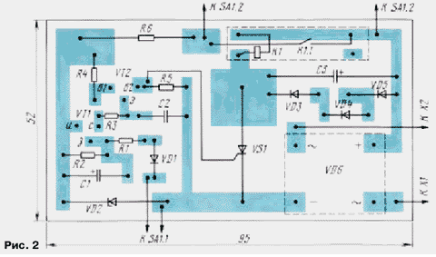
Most of the parts of the machine are placed on the PCB of unilateral foil fiberglass, a sketch of which is shown in Fig. 2.

Can use transistors KPA (VT1) and CT(A-G) (VT2), SCR - KUN, diode VD1 - KDA, KDA, KDA, KDA, KDB and other similar, Zener - voltage stabilization 12...15 V and operating current of at least 20 mA. Capacitors C1, C3 - C50-24, K53-14, C2 - KLS, km-5 and similar, resistors - MLT, S2-33. The switch SA1 - P2K, MT-3.
Relay K1 - RES-55 (passport RS4.569.603) with a winding resistance of 95 Ohms and a voltage of about 2.5 V, REF-44 (RS4.569.251 with parallel connection of windings), RES-10 (RS4.524.304) winding resistance 45 Ω and RES-9 (RS4.524.203) with a winding resistance of 30 Ohms. When choosing a relay note that the current its deployment should be less than the current consumed with lighting lamps, and the current release is less than the leakage current of SCR.The number of series connected diodes VD3-VD5 must be such as so that the voltage on the relay consistent with its voltage. Choose diodes and VD6 diode bridge must withstand the current consumed by the lamps. When using these in the diagram diodes lamp power can reach 220 W, and the SCR will not require a heat sink. In the case of heavier loads have to use and more powerful diodes, and SCR to be installed on a heat sink. The capacitance of the capacitor C3 should be increased to two or three times, if the resistance relay coil will be less than 80...90 Ohm.
The build machine is to install on-time lamps (selection resistor R1) and time delay disabled (selection resistor R2 and smoothly capacitor C1 rough). Flat gas discharge (TN-0,2, TN-0,5, MN-3, D.) lamp HL' is needed in the case when the machine is placed in a dark room and it is necessary to designate its location. The resistance of the resistor R" depends on the type of lamp. If you need to have a smooth manual adjustment the brightness in the machine it is necessary to introduce a resistor R' - 100 ohms (SP-0,4, JS4-3), setting it on the front panel. It can be combined with switch and SA1.
As already noted, the machine include instead of the regular switch (contacts X1, x2) in series with the load. If you use a separate transaction the supply voltage fed to the contacts x2, X3, and the load connected to the jacks XS1.
All of the elements of the device are at mains voltage, so its design should avoid contact of parts in operation. Should be extremely careful when adjusting. All replacement elements, soldering, connecting the measurement devices should be carried in completely unplugged the device, it is necessary to unplug the plug, which it is included in the network.
Author: I. Nechaev, Kursk


